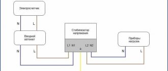
The basis of modern voltage stabilizers is an automatic transformer.
Control of the load supplied to its windings in order to normalize the output current parameters is carried out by relay, servo-drive or electronic methods. The latter ensures noiselessness, low inertia and the highest stabilization accuracy. Moreover, the device requires almost no maintenance and can serve for more than 15 years. As a result, the demand for electronic devices is growing by leaps and bounds, despite the continued high cost.
Design and principle of operation of thyristor and triac stabilizers
The main components of these voltage stabilizers are:
- power autotransformer - used to correct the mains voltage;
- electronic control circuit (usually implemented on a microprocessor basis) – controls all functions of the stabilizer in accordance with signals from sensors of network parameters and load power consumption;
- block of switching power semiconductor switches (thyristors or triacs) - used for switching taps of the windings of a power autotransformer;
- network interference filtering devices – suppress pulse and high-frequency interference.
On the body of electronic stabilizers, as a rule, there is an LCD display and LED indicators that display the values of the operating parameters of the device: voltage values at the input and output, power of the connected load.
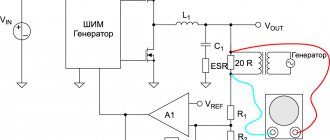
The operating principle of thyristor and triac stabilizers is the same. The input alternating mains voltage is supplied to a converting autotransformer - a type of transformer whose primary and secondary windings are connected, that is, they are not only electromagnetically coupled, but also electrically connected. The secondary voltage is removed from one of several terminals of the autotransformer winding. Connection to each terminal uses a different number of turns of the transformer coil, which will determine the transformation ratio and, accordingly, the output voltage. The most similar operating principle is the relay type of stabilizers.
The parameters of the input and output voltage of the autotransformer are constantly monitored by the microprocessor of the control board. If they deviate from the norm in any direction, the microprocessor sends a control signal to turn on a specific power switching device - a semiconductor switch. Depending on the type of power switches used, a distinction is made between thyristor (using thyristors) and triac (respectively, using triacs) devices.
Contents
I was interested in this information, I remembered that in the cinema "Ukraine" there was also continuous voltage switching - there, during the switching period, a wirewound resistor was connected between adjacent contacts of the switch. I started looking on the Internet for anything useful about this. I was not able to get acquainted with invention No. 2356082.
I managed to find an article “Types of voltage stabilizers”, which talked about the possibility of connecting a diode to the relay contacts at the moment of switching. The idea is to switch the AC voltage during the positive half-cycle. In this case, you can connect a diode in parallel with the relay contacts for the switching period.
Based on this article, the most common relays were taken and the switch-off time, the time spent in the broken state and the switch-on time were measured. During the measurements, I saw contact bounce on the oscilloscope, which caused a lot of sparking and erosion of the contacts, which sharply reduces the service life of the relay.
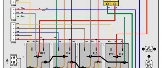
To implement and test this idea, a 2 kW AC relay stabilizer was assembled to power the apartment. Auxiliary relays connect the diode only for the duration of the main relay switching during the positive half-cycle. It turned out that the relays have significant delay and bounce times, but, nevertheless, the switching operation was managed to fit into one half-cycle.
Read also: Connecting a schneider telephone socket
Thyristors and triacs. What is the difference?
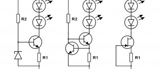
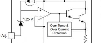
Thyristors and triacs are semiconductor elements, the control of which (changing their switching state) is carried out by applying a positive potential to the control electrode. Their difference lies in the number of layers with different conductivities in the element plate.
The thyristor is a unidirectional AC converter. In its structure, the element has a control electrode, an anode and a cathode.
A triac is two back-to-back thyristors that are located parallel to each other. In a triac, each electrode is an anode and a cathode at the same time, due to which this semiconductor switch is capable of conducting current in two directions.
Next, we will consider the features and differences of devices with switching implemented on thyristor and triac switches.
↑ Files
Hello, reader! My name is Igor, I'm 45, I'm a Siberian and an avid amateur electronics engineer. I came up with, created and have been maintaining this wonderful site since 2006. For more than 10 years, our magazine has existed only at my expense.
- Thank you for your attention! Igor Kotov, editor-in-chief of Datagor magazine
Ivan Vnukovsky, Ukraine, Dnepropetrovsk
Operation scheme, strengths and weaknesses of thyristor stabilizers
Let's take a closer look at the operating algorithm of the thyristor stabilizer:
- When changing the input current parameters, a delay phase (up to 20 ms) is used to measure the value of the input network voltage.
- Having compared the actual and permissible current characteristics, if necessary, the control board processor issues a command to correct the output voltage:
- in cases where input voltage deviations are within the permissible range, it is corrected to the required value;
- In case of voltage surges outside the permissible range, the protection system ensures emergency shutdown of the device.
Thyristor voltage stabilizers have the following advantages:
- relatively high performance – 20 ms (compared to relay devices);
- high efficiency, which is achieved due to the absence of relays and moving elements;
- ability to function in an external environment with high or low temperatures;
- durability and reliability due to the absence of mechanical parts;
- silent operation;
- overload resistance.
Thyristor devices are also distinguished by a fairly high accuracy of output voltage stabilization (from 5 to 10%) compared to relay models, as well as a relatively wide input voltage range, which allows them to be used in networks with extremely low-quality voltage.
A serious disadvantage of thyristor stabilizers is the discreteness (steps) of voltage correction. Stepped voltage surges that appear when switching transformer windings impair the accuracy of stabilization and reduce the operating speed of the device.
Due to these disadvantages, thyristor stabilizers cannot be used to power loads that are particularly sensitive to voltage changes (for example, PCs and peripheral devices, professional audio and video devices, as well as electronically controlled devices).
In addition, the output voltage of thyristor stabilizers has a shape other than sinusoidal (trapezoidal or with other distortions, depending on the specific model), which makes their use undesirable to power loads with electric motors (for example, pumps, heating systems).
Popular brands
| Model | Parameters / Power | Information |
| Leader W |
Power: | No |
| Energy Premium |
Power: | Go >> |
Scheme of operation, advantages and disadvantages of triac stabilizers
Triac voltage stabilizers have an operating principle similar to thyristor devices.
Their obvious advantages, of course, include the above-listed advantages that distinguish thyristor devices:
- speed and accuracy of voltage regulation;
- high efficiency value;
- silent operation (which is especially important when installed in residential areas);
- long-term service life;
- reliability of operation due to the complete absence of mechanical moving parts.
Modern triac voltage stabilizers, like their thyristor analogues, are distinguished by a wide input voltage range and the ability to operate at fairly low temperatures.
Their significant disadvantages are their high cost compared to relay models and stepwise regulation of the output voltage. The disadvantages also include the greater bulkiness of power switches compared to thyristor analogues: one triac occupies an area sufficient to accommodate several thyristors. Of course, this does not have a positive effect on the overall dimensions and weight of the devices.
Comparing the types of semiconductor switches used, we add that triacs are less resistant to current overloads and during operation can heat up much more, which increases the risk of their failure.
Triac stabilizers have the same application restrictions as thyristor ones. They cannot be called a good solution for organizing the protection of electric motors or loads with an electric drive due to the distortion of the output signal shape: as a rule, this is a modified sine wave. Speaking about limitations in use, it is worth adding their low resistance when working with an inductive load.
Attention!
When purchasing a triac stabilizer to power voltage-sensitive electrical devices, it is necessary to clarify the number of power semiconductor switches involved in the stabilizer circuit - the more there are, the more the device will be able to provide an output voltage closer to the rated value.
Let's sum it up
Comparing triac and thyristor voltage stabilizers with each other and with other types of devices, we can come to the following conclusions:
- both types of devices have both similar capabilities for voltage stabilization and almost identical disadvantages, one of which is stepwise adjustment and, as a consequence, a non-sinusoidal shape of the output signal;
- these stabilizers cannot protect equipment sensitive to network quality, as well as devices with electric motors;
- both devices are not much superior to relay voltage stabilizers in their operating parameters, but their cost is much higher;
- If thyristor and triac devices break down, repairing their electronic components will cost more than previous generations of voltage stabilizers operating on a similar principle.
Inverter stabilizers as an alternative to thyristor and triac ones
Despite the fact that triac and thyristor stabilizers are still quite popular, they are gradually but surely being forced out of the market by a new type of device - inverter voltage stabilizers. These devices were developed in 2015 and are rightfully considered products of a new generation.
Inverter models, unlike triac and thyristor models, operate on a completely different principle. The circuit of their operation does not include an autotransformer or any switching elements. Voltage correction is performed using a rectifier, capacitor and inverter. First, the input alternating voltage is transformed into direct voltage, and then again into alternating voltage, but already having reference characteristics. Thanks to double conversion technology, these devices can:
- instantly respond to network deviations in the range of 90-310 V;
- stabilize voltage with high accuracy (2%);
- supply a voltage of an ideal sinusoidal shape to the load;
- uninterruptedly power electrical appliances during short-term network outages (up to 200 ms).
The high technical characteristics of inverter stabilizers allow them to be used for the most demanding consumers in terms of power quality in networks with significant voltage fluctuations.
Currently, the Russian manufacturer of power supply systems "Shtil" offers the following models of inverter voltage stabilizers:
- single-phase devices for wall and floor/rack installation with an output power of 0.35-20 kVA;
- 3-in-1 configuration models of floor/rack installation with an output power of 6-20 kVA, designed to operate in a three-phase network to power a single-phase load;
- three-phase floor/rack mounted devices with an output power of 6-20 kVA.
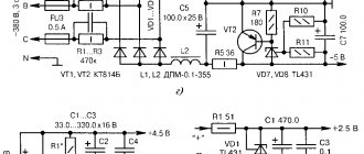
↑ Program
The program is written in SI language (mikroC PRO for PIC), divided into blocks and provided with comments. The program uses direct measurement of alternating voltage by a microcontroller, which simplifies the circuit. Microprocessor used PIC16F676
.
zero
program block waits for the appearance of a falling zero crossing. At this drop, either the alternating voltage value is measured, or the relay begins to switch.
izm_U
program block measures the amplitudes of the negative and positive half-cycles
In the main program, the measurement results are processed and, if necessary, a command is given to switch the relay. For each relay group, separate turn-on and turn-off programs are written, taking into account the required R2on
,
R2off
,
R1on
and
R1off
. The 5th bit of port C is used in the program to send a clock pulse to the oscilloscope so that the results of the experiment can be viewed.