Pass-through switch circuits allow you to turn lighting on and off from two or more different locations. In some cases this is not just convenient, but also very necessary.
For example, there is a long corridor in the room. It is naturally illuminated. By turning on the light at the beginning, and having this same connection diagram for the pass-through switch , you will not have to return again to turn it off, but you can do this with the second switch, which is installed at the other end of the corridor. Very often, such circuits are also used to control the lighting of stairs.
What is better to use: pass-through switches or bistable relays? The answer is here.
How to correctly connect pass-through switches for independent lighting control from two places.
Let's take a closer look at this connection diagram, consisting of two pass-through switches . It requires two switches (also called “pass-through”), each of which has three contacts and two switching positions. Moreover, the switching mode must be “change-over”, that is, one contact is common to the other two. In one position it is closed with one of them, and in another position, naturally, with the other. Consequently, the general short circuit of all three contacts is completely eliminated.
Connection diagram for a pass-through switch for controlling a lamp from 2 places
Pass-through switch with three contacts and two positions (the common contact is on top)
Explanations for the diagrams
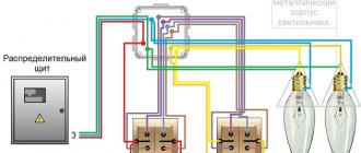
Now let's look at the drawn diagrams. Both circuits consist of a connection box, the pass-through switches themselves, a lamp and connecting wires (during installation, these will be two, three and four-core cables). The first diagram shows a connection diagram for a pass-through switch with control from two different places.
As you can see, one wire (in our case it is neutral) goes from the power source to the junction box and from there to the lamp. The other (phase wire), after the box, is connected to the common contact of one of the switches. Two switched contacts of one switch are connected to two contacts of the second switch (via a box). Well, from the common contact of the second switch, the phase is supplied to the second contact of the lamp.
As for the installation of this circuit itself: pass-through switches , from which three-core cables are output. Lamps are mounted that are connected in parallel and from which a two-core cable ultimately comes out.
Next, a connection box is installed in the most suitable location (taking into account the minimum cable length and the convenient location of this box). The cable from the lamps, power supply and the pass-through switches themselves is inserted into it. In this box the wires are connected to each other, as shown in the diagram.
Connection diagram for a pass-through switch for controlling a lamp from 3 places
How to control lighting from three places
The connection diagram for a pass-through switch with control from three places is not much different from the previous one (the general operating principle is the same). It adds another pass-through switch, which is slightly different from the previous ones. As can be seen from the diagram, this is a twin switch . That is, when one key is pressed, two contacts that are electrically independent of each other are simultaneously switched. In addition, as you should have noticed, there is a four-wire cable coming out of it.
Connection diagrams for pass-through switches of this type are good because they are relatively simple in their design (no additional components are required). But they are limited by the number of such control places.
The problem of independent lighting control from two places can also be solved using special pulse relays and units for remote lighting control.
Other ways to implement lighting control from two or more places:
Source: electric.info
How to connect a pass-through switch (light control from two or more points)
Current electricity prices make you think about saving where you never even thought about it before. For example, lighting on the stairs. It doesn’t matter if it’s in a private or multi-storey building, you still need to pay. Previously, they simply left the light on. Today you think about turning it off, but running up and down is also not fun. It turns out there is a solution. To prevent the lights from being on constantly, there are schemes for controlling the lamps from several places. That is, one or more lamps can be turned on and off from several points. Special switches are needed for this. They are called walk-throughs. Sometimes the names “duplicate” or “change-over” are found. All this is one type of electrical equipment. They differ from ordinary ones in a large number of contacts. Accordingly, the connection diagram for the pass-through switch is more complicated. However, you can figure it out.
What does a pass-through switch look like and work?
If we talk about the front side, the only difference is: a barely noticeable arrow on the up and down key.
What does a single-key pass-through switch look like? You see there are double arrows
If we talk about the electrical circuit, everything is also simple: in ordinary switches there are only two contacts, in pass-through switches (also called changeover contacts) there are three contacts, two of which are common. There are always two or more such devices in the circuit, and they are switched using these common wires.
The difference is in the number of contacts
The operating principle is simple. By changing the position of the key, the input is connected to one of the outputs. That is, these devices have only two working positions:
- input connected to output 1;
- input is connected to output 2.
There are no other intermediate provisions. Thanks to this, everything works. Because the contact switches from one position to another, electricians believe it is more correct to call them “switches.” So a pass-through switch is also this device.
In order not to rely on the presence or absence of arrows on the keys, you need to inspect the contact part. Branded products should have a diagram on them that allows you to understand what type of equipment you have in your hands. It is definitely found on products from Lezard, Legrand, and Viko. They are often absent on Chinese copies.
This is what the changeover switch looks like from the rear
If there is no such diagram, look at the terminals (copper contacts in the holes): there should be three of them. But not always on inexpensive copies the terminal that stands alone is the input. They are often confused. To find where the common contact is located, you need to ring the contacts with each other at different key positions. This must be done, otherwise nothing will work, and the device itself may burn out.
You will need a tester or multimeter. If you have a multimeter, set it to sound mode - it beeps when there is contact. If you have a pointer tester, ring for a short circuit. Place the probe on one of the contacts, find which of the two it rings with (the device beeps or the arrow shows a short circuit - it deviates to the right all the way). Without changing the position of the probes, change the position of the key. If the short circuit is missing, one of these two is common. Now all that remains is to check which one. Without switching the key, move one of the probes to another contact. If there is a short circuit, then the contact from which the probe was not moved is the common one (this is the input).
It may become clearer if you watch a video on how to find the input (common contact) for a pass-through switch.
How to connect a hob is written here, and how to install and turn on a water heater is written in this article.
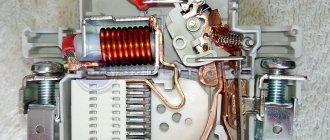
Switch design and characteristics
The device is equipped with a durable housing, the filling of which consists of blade movable contacts attached to the shaft, a control lever, an arc extinguishing compartment, stationary type contacts, as well as terminal parts for connecting to the network.
The device has three contacts, two of which are active, and the third is neutral, ensuring complete disconnection of the load from the power line.
Switching on occurs according to a simple scheme: the central conductive line is connected to the first contact, and a diesel or gasoline generator is connected to the second. The most popular switches are considered to be 2 and 4 poles. Basic rules for connecting a switch indoors from a three-phase power supply :
- Choose a four-pole device.
- The 4 available terminals are connected to the input network.
- The other 4 terminal elements are connected to the generator.
- Connecting copper parts are used to connect the load.
Three of the four terminals are for phase, and the last one is for zero. The reversing switch has the following characteristics :
- filling elements do not collapse under high temperature;
- a short fluctuation in the network will not put the device out of service;
- high-quality insulation eliminates electrical shock;
- Manufacturers produce devices with rated currents from 15 to 125 A
- By switching a large number of poles can be switched.
According to the recommendations of electricians, the switch can be used for a long time, since it has an impressive number of switching cycles.
Two-way and three-way devices
For single-phase electrical circuits, two-way devices are used. The switches are equipped with pass-through capacitors and two or three modules. Together with the switch, a 300-volt power supply can be used simultaneously in operation.
The switch is installed in almost all types of electrical panels. It is strictly forbidden to expose the device to overvoltage above 350 volts. The average load is 30 A.
For industrial organizations with a two-phase circuit, three-way switches are used. They are more functional and are equipped with blockers . These device models have increased sensitivity and in case of significant overload, thanks to the protection system, they will not fail. They are sold at a higher price than the first version of the products.
3 point circuit
To be able to turn the light on/off from three places, you need to buy a cross (cross) switch for two switches. It differs from those described earlier by the presence of two inputs and two outputs. It switches a couple of contacts at once. See the figure for how everything should be organized. If you understand the above, this one is easy to understand.
Electrical circuit for controlling a lamp from three points
How to assemble such a circuit? Here's the procedure:
- Zero (and ground, if any) is connected directly to the lamp.
- The phase is connected to the input of one of the pass-through switches (with three inputs).
- The input of the second is fed to the free wire of the lamp.
- The two outputs of one three-pin device are connected to the input of a crossover switch (with four inputs).
- The two outputs of the second three-pin device are connected to the second pair of switch contacts with four inputs.
The same diagram, but from a different perspective - where to connect the wires on the housings.
Where to connect the wires
And this is approximately how to distribute it around the room.
Wiring when controlling the lamp from three places
If you need a circuit with four, five or more points, then it differs only in the number of cross switches (for four inputs/outputs). There are always two switches (with three inputs/outputs) in any circuit - at the very beginning and at the very end of the circuit. All other elements are cross devices.
Connection diagram for pass-through switches for 5 points
Remove one “crossbar” and you get a four-point control scheme. Add more and there will be a scheme for 6 control places.
To finally get it all in your head, watch this video.
Is it possible to control lighting from more than 2 places?
The answer to this question is of course yes. However, for these purposes, it is necessary to additionally include a crossover switch in the circuit. You can see the control diagram for lighting systems from three places in the following photo:
A single-line connection diagram using this method looks like this:
As you can see from the photo above, the main difference in lighting control between 2 and 3 place controls is the presence of a crossover switch and more connected wires in the junction box. Also, to connect a cross switch, it is necessary to use a cable with 4 cores or with 5 if there is a ground loop.
Two-key pass-through switch: connection diagram
To control the lighting of two lamps (or groups of lamps) from one switch from several places, there are two-key pass-through switches. They have six contacts. If necessary, find the common wires using the same principle as in a conventional device of this type, only you will have to connect a larger number of wires.
The connection diagram for a 2-key pass-through switch differs only in that there will be more wires: the phase must be supplied to both inputs of the first switch, just as from the two inputs of the second it must go to two lamps (or two groups of lamps, if we are talking about a multi-arm chandelier ).
The principle of connecting two-key pass-through switches
If you need to organize control of two light sources from three or more points, you will have to install two cross switches at each point: there are simply no two-key switches. In this case, one pair of contacts is placed on one crossbar, the second on the other. And then, if necessary, they are connected to each other. The outputs of both crossbars are connected to the last two-key transition switch in the chain.
How to organize control of two lamps from four places
If you think about it, everything is not so complicated, and the connection diagram for a pass-through switch from 2 points is generally simple. Just a lot of wires...
Source: stroychik.ru
Reversing switches for the home - description and principle of operation
If it is necessary to distribute the load across several parallel lines in a three-phase or single-phase circuit, use a reversing switch (also known as a reversing switch or circuit breaker). The device has a simple design and is completely safe for the technician at the time of its use. The machine can only be controlled manually.
- Definition and purpose of a reversing switch
- Switch design
- Types of switches
- Specifications
- Device installation
- Recommendations for use
Connecting a pass-through switch: how to do it correctly?
Pass-through switches allow you to control one lighting device from different points: for example, turn on the light at the entrance to the room, and turn it off while lying in bed. How to connect a pass-through switch? We explain in detail with diagrams and examples.
Pass-through switches are very convenient when you need to turn a light bulb on and off from different points in an apartment or house. For example, at the beginning of a corridor you can turn on a light bulb, and after passing through it, turn it off at the other end. Or on the first floor, light the lamp on the stairs, and when you get to the top, turn it off. How to properly install a pass-through switch so that everything works like a clock? We explain in detail with diagrams and examples.
What is required to connect a pass-through switch?
In order for the circuit to work, we need the following components:
- Two pass-through switches.
- Three-core wire type VVGng 3*1.5 mm 2 or NYM 3*1.5 mm 2
- Lamp.
- Phase + zero from the shield.
Pass-through single-key switches, unlike ordinary ones, have not two contacts, but three, so it will not be possible to use ordinary switches for such purposes. Conventional two-key switches also have three contacts, but they are also not suitable for pass-through installation, since they work differently.
Connection diagram for pass-through switch
In order for the entire circuit to work properly, it is necessary to correctly connect the wires to the terminals inside the switch. In any pass-through single-key switch, the terminals are indicated by arrows: one will go inside the switch (phase) and two outside (output), as shown in the figure below. If you mix up and connect the phase wire to the arrow that goes out, the circuit will not work correctly.
The connection diagram for the pass-through switch is as follows: zero from the meter is supplied through the distribution box directly to the light bulb. The phase from the meter is supplied to switch 1; two outputs of switch 1 are connected to the outputs of switch 2; phase from switch 2 goes to the light bulb. Pay attention to diagram 1: here the contacts on the switch are open, so the light bulb is off.
Suppose a person passing through the corridor turns on switch 1, thereby closing the circuit and turning on the light bulb. In this case, the diagram becomes like this:
At the end of the corridor he presses switch 2, the circuit opens and the light bulb turns off (diagram 3). In this case, in order to turn on the light bulb again, he does not need to return to switch 1 - just press the button of switch 2.
With this scheme, the light bulb can be controlled by any switch, without even using the second one. Now let's see how to connect the switch directly to the junction box.
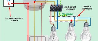
Connecting a pass-through switch in a distribution box
In the distribution box we see 10 wires: 2 come from the switchboard, 2 from the light bulb and 3 from each switch. We connect the wires as follows: we connect the blue zero ( 1 ) from the panel board directly to the blue zero ( 1 ) of the light bulb. the phase from the switchboard ( 2 ) to the white wire ( 2 ) of the first switch. Then the red output ( 3 ) of the first switch with the red output ( 3 ) of the second. We also connect the green wires ( 4 ). the white wire ( 5 ) of the second switch to the phase wire ( 5 ) of the light bulb. We wrote here how to properly connect wires.
In some apartments there is also a yellow-green ground wire coming from the switchboard. It does not fit into the pass-through switches, but is placed on a separate terminal. Once everything is connected, apply power from the electrical room and check the operation of each switch. If anyone can turn the lamp on and off, then the circuit is connected correctly.
Operating principle
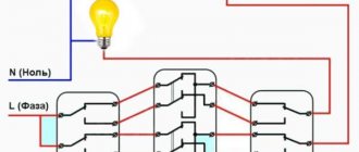
Below is a diagram for connecting intermediate switches, providing independent switching on and off of lights from two different places.
Zero is connected directly to the lighting device, the phase is connected through a pair of switches connected by a two-wire conductor. With two switches PV1 and PV2, the first and third contacts close, as a result the circuit is closed, and electricity flows into the lamp.
To open the chain, press the button of any switch, for example, PV1. As a result, the first and second contacts will close. When you press the PV2 switch button, the same thing happens. Thus, we obtain a lighting system that is independently controlled from different points.
Pass-through switch connection diagram
Conventional switches that are installed in our homes are capable of turning lights on and off from one place. Agree that the chandelier, which is located in the bedroom, can only be turned on with the switch, which is located there.
But what to do if you need to control one lamp from different rooms at the same time. It is difficult to assemble such a circuit using conventional switches. Pass-through switches, or switches as they are also called, will come to the rescue.
Such switches are used to organize control of lamps independently from several places. The proposed connection scheme is not only very convenient, but also allows for quite significant energy savings.
In this article, let's look at how to assemble a circuit diagram for connecting a pass-through switch in a distribution box.
The use of walk-through switches to control the lighting of staircases is especially important. Often, circuits using time relays are used for this purpose, but it should be recognized that they are not so convenient to use, less reliable and economical.
Everyone moves up stairs at different speeds, and you yourself can climb light today, and tomorrow with a heavy suitcase. Setting large time delays taking into account the reserve means reducing savings.
The proposed scheme allows you to turn on the lamps below with one switch, and when going up the stairs, turn them off with another. If you need to go downstairs, you use the walk-through switch at the top to turn on the light and at the bottom to turn it off. It is also convenient to use a similar scheme for lighting long corridors.
However, pass-through switches will be useful not only for owners of long corridors and multi-story buildings. They will also be very useful for residents of small apartments. Typical situation. Your apartment has a walk-through room, when entering which you turn on the light, then go to the next room, turn on the light in it, and turn off the lighting in the walk-through room that has become unnecessary. Agree - very convenient. Eliminates unnecessary walking and saves electricity.
One more example. You go into the bedroom and turn on the light at the door. When you go to bed, you turn on the table lamp or sconce to read a book before bed, but now you have to get up again, go to the door and turn off the chandelier! But you don’t have to do this if you have previously installed a pass-through switch at the head of the bed.
To implement such a control scheme, so-called “pass-through switches” are used, which, strictly speaking, are actually switches. Unlike conventional switches, they have not two, but three contacts and can switch the “phase” from the first contact to the second or third.
Any type of lamp can be used as a light source in such a scheme - from conventional incandescent lamps to fluorescent, energy-saving and LED. However, using the same scheme, you can connect not only lamps, but also any other load, the activation of which you need to control from several places.
Starter capabilities
The situation that an ordinary person most often encounters in practice is the need to assemble a circuit for connecting the reverse of an asynchronous AC electric motor or a DC commutator motor.
At the same time, electromagnetic waves arise in it. The starter has wider functionality than the basic contactor and, in addition to providing frequent starts and stops, can act as a protective barrier during overloads. Their boundaries are indicated by dashed lines in the diagram; Stop, Start - controls the block itself is highlighted with a dashed line. For example, only KM1 or, on the contrary, KM2 can function. This article discusses in detail the step-by-step operation of the circuit.
There is a small air gap between the rotor and stator, thanks to which unhindered displacement is possible. Switching circuits for a reversible magnetic starter The operating principle of switching circuits for a reversible magnetic starter To change the direction of rotation of an asynchronous electric motor, it is necessary to change the phase sequence of the stator winding.
Any magnetic starter consists of the following main parts: Electromagnetic part. They are used in various machines, as an electric drive, in conveyors, lifting mechanisms, pumps and fans. The contactor performs the same role as the starter.
How to connect a pass-through switch - control circuit for a lamp from 2 places
The procedure for connecting a pass-through switch is not much different from connecting a conventional switch. The only difference is in the number of contact terminals and wires supplied. The pass-through switch has three of them.
Please note in advance that you need to stretch a three-core wire from the junction box to such a switch.
Pass-through switch connection diagram - control of a lamp from 2 places
The circuit uses two pass-through switches and a distribution box into which wires from the controlled lamp and three-wire wires from the switches are inserted.
The phase wire from the junction box is connected to the common input contact of the first pass-through switch. The other two (output) contacts are connected to wires coming from similar contacts of the second switch. And the common (input) contact of the second switch is connected to the wire coming from the lamp.
The second wire from the lamp is directly connected to the junction box zero.
The cross-section of the three-core wire supplied to the pass-through switches must be selected in accordance with the power of the controlled luminaire.
Manual changeover switches OT series from ABB
Reversing load switches play a key role in uninterruptible power supply systems for consumers. Their functional purpose is a smooth and safe transition of the consumer from the main power source to the backup one.
Main technical parameters:
- Number of poles: 3 - 4
- Rated continuous load current Iu: 16 – 3200A
- Rated operating voltage Ue AC: 750-1000V
- Dielectric strength: 6-10kV
- Rated impulse withstand voltage: 8-12kV
- Degree of protection (IP) of the front side: IP20-IP65
Key benefits
Complex offer
ABB offers a wide range of transfer switches in the current range from 16 to 3200A for manual control of the following types: zero, non-zero or fast changeover. The most complete range of devices is expanded by a large number of accessories from control handles and auxiliary contacts to control controllers, which allows you to use different combinations of poles and handles, giving you the opportunity to create convenient and unique solutions.
Unsurpassed reliability and high performance
ABB transfer switches are designed, manufactured and tested for maximum performance. They have a Comparative Tracking Resistance Index (CIT) of over 600V, which ensures reliable operation in any conditions and requires virtually no maintenance throughout their entire service life. Durability proven by tests in accordance with IEC 60947-6-1.
Compact design
All devices are designed for quick and easy installation and maintenance. The modular design and small overall dimensions allow the use of smaller shells, thus saving space, materials and installation time. The simple design makes it easy to operate even by untrained personnel.
Safety
ABB transfer switches are supplied with a large number of built-in interlocks, increasing the safety of the solution. To prevent unauthorized switching (remote or manual) and safe operation, the device can be locked with a padlock even with the handle removed.
Typical Application
The most common application of reversing load switches is to switch consumers between two power sources.
How to connect a pass-through switch - control circuit for a luminaire from 3 places
In certain cases, it becomes necessary to provide not two, but more control points for lamps. For example, the light on the stairs of a multi-story building must be turned on and off on each floor. The same situation occurs with a long corridor into which the doors of several rooms open.
It is possible to implement such a scheme, but in addition to simple pass-through switches, you will also need cross switches. Such switches no longer have three, but four contacts - two input and two output, representing two pairs of simultaneously switched contacts. Accordingly, a four-wire wire must be connected to such switches.
Pass-through switch connection diagram - control of a lamp from 3 places
In this control scheme, conventional pass-through switches are used at the first and last control points of the lamps and cross switches at all the others.
The number of control points is not limited; only the complexity of switching in the distribution box increases due to the large number of wires connected to it. And here you cannot do without proper marking of the wires when laying them, otherwise you will simply get confused in them.
The connection principle is as follows: the output pair of contacts of the first pass-through switch is connected to the wires going to the input pair of the next cross switch, and so on, up to the last pass-through switch, the common contact of which is connected to the wire going to the lamp. The phase wire is connected to the input contact of the first switch, and the second wire from the lamp is connected to the zero of the junction box.
We stretch a three-wire wire to each pass-through switch, and a four-wire wire to each crossover switch.
The diagram presented shows the connection of three lighting control points, consisting of one crossover and two pass-through switches.
A little clarification on the connection diagrams
Let's look at how the pass-through switch connection diagram . The presented diagrams use the following elements: connection box, lamp, pass-through switches and connecting wires, for which, during the installation process, cables of different designs are used.
The first of the proposed circuits represents the connection of a pass-through switch, in which control is carried out from two different locations; this type of circuit is considered quite simple to implement.
With this type of connection, one wire, which is neutral, is directed from the source of electricity to the lamp through the junction box. The second, which is phase, is also directed through the junction box to the switch contact.
Thus, two pairs of switch contacts are connected to each other. To light the lamp, the phase is supplied to the lamp from the common contact of the second pass-through switch.
The second diagram shows the connection of pass-through switches together with a changeover or cross switch. This scheme makes it possible to control lighting from three different places.
We’ve figured out the connection diagram, now let’s learn more about its installation. It consists of installing pass-through switches and further laying three-core cables from them. Lamps connected in parallel are also installed, from which a two-core cable extends.
At the same time, we also install a junction box, where we lay cables from: switches, lamps, and power supply, to connect them together, in accordance with the above diagram. In this case, you should pay attention to choosing a suitable location for installing the junction box, taking into account the length of the cables used.
I hope this article “ pass-through switch connection diagram ” helped you deal with all the connection issues, if you have any questions or suggestions, ask them in the comments, I will be happy to answer.
Three-point lighting control option
If there is a need for remote control of the lamp from three places, then you will also have to purchase a cross switch. It switches not one, but two contacts at a time, so it has two inputs and two outputs.
How to connect all three switches can be seen in the figure. This is somewhat more complicated than the previous case, but you can understand the principle of operation.
Electrical diagram for switching on a lamp from three places.
To connect an electric light source, according to this diagram, you must perform the following operations:
- The neutral wire is connected to one of the lamp wires.
- The phase wire is connected to the input contact of one of the pass-through switches.
- The free wire of the lamp is connected to the input contact of the second switch (pass-through).
- The two output contacts of the pass-through switch are connected to the two input contacts of the crossover switch.
- The two output contacts of the second pass-through switch are connected to the two output contacts of the crossover switch.
The diagram is the same, but it is shown more clearly where exactly to connect the wires.
Which terminals are the wires connected to?
This is approximately how you should route the wires around the room.
Based on a circuit for three control points, you can assemble circuits for 4 or 5 points. In such cases, it is necessary to increase the number of crossover switches. They should always be installed between two pass-through switches.
Scheme of organizing on/off lamp for 5 points.
If you remove one of the cross switches from this circuit, you get a 4-point option, and if you add one cross switch to it, you get a 6-point option.
Pass-through switches from 5 places without junction boxes. Suneler.ru
What is the difference between a pass-through switch and a regular switch?
If you look at the pass-through switch from the side, you will not find any external differences. The significant and only difference between such switches and simple ones lies within their design.
A conventional single-pole single-key switch has two contacts in its design, fixed and movable. The moving contact is driven by a key that we press by hand and closes with the fixed contact. This closes the electrical circuit and supplies power to the lamp. There are also designs of two-pole single-key switches that essentially perform the same function as the previous one. Its difference is that the neutral wire going to the lamp breaks in the same way as the phase wire. This was done to improve security.
Figure 1. Schematic diagram for connecting single-pole and double-pole single-key switches
The pass-through switch has two fixed and one moving contacts. The moving contact is always closed with one of the fixed ones. When you press a key and move it from one position, for example, "off" to another position - "on", the moving contact also changes its position, opening with a closed contact and closing with an open one. That is, the pass-through switch does not have an “off” position and it works not as a switch, but as a switch. Therefore, in technical literature and in manufacturers’ catalogs it is correctly called a switch. For example: “single-pole, single-gang, double-throw switch.” Keep this in mind when you buy switches to assemble a control circuit from two places.
In addition to single-pole switches, there are double-pole and even three-pole switches. For ease of understanding, in this article we will use the expression not a switch, but a pass-through switch, since it is more often used among people.
Specifications
We will not consider all the parameters of the device here, because the choice is always made based on the size of the starter, which is characterized by the rated load current acting on the contacts of the device. There are seven starter values, each of which corresponds to the permissible current load. The photograph below shows these same values and in what areas such magnetic starters are used.
It should be noted that small errors in the parameters are acceptable. But in some cases it is necessary to take into account the range in which the thermal relay operates. If the starters have an overestimated load, and the relays have an underestimated minimum thermal shutdown value, then there may be a mismatch with the specified power of the electrical circuit or consumer.
vote
Article rating
Where is a similar lighting control system used?
The lighting control system most often considered is used in public and industrial premises, namely: in long corridors, tunnels, walk-through rooms, that is, in rooms where there are two doors equally serving as entrance and exit, in staircases and other places. In all of the above cases, pass-through switches are installed next to the doors.
If we talk about residential premises, then the installation location for pass-through switches can be, for example, the entrance door to the room and a place on the wall next to the bedside table. In this case, a person entering the room will turn on the light by pressing the pass-through switch located next to the door, and sitting on the bed, without getting up, he can turn it off with the second pass-through switch located next to the bed.
Using pass-through switches, you can control one luminaire or lamp, or a group of them. For each case, different types of pass-through switches are used (single-key, two-key, three-key). The main goal that a person pursues when installing such switches is the convenience of light control and reducing energy costs.
Design features
Structurally, a cross switch with one key is a compact switching device that operates from mechanical action on it. At the same time, the same touch-sensitive switching elements are also available for sale; they do not have a key, but only a touch button, but the essence of the device’s operation remains the same. Only the mechanism of action changes, but the contact group and principle of operation remain the same. The crossover switch consists of:
- output contact terminals for connecting wires;
- wall mounting mechanism;
- conductive jumpers located inside the housing;
- contact groups;
- mechanism of influence on the contact switching group.
According to the installation method, these switches are divided, like all others, into those intended for open (external) and hidden (laid inside walls) wiring. That is, the design can be of two types: overhead and built-in.
Very rarely, in exceptional cases, hybrid wiring is used, when the entire cable line is laid in a hidden way inside the walls, and the switches are installed externally, that is, overhead type. This special case occurs when it is not possible to make niches for trimmers or their implementation is problematic.
Cross switches look like ordinary pass-through switches and do not have a clear on or off position. Their difference is:
- There are four contact terminals for connection. If there are two control keys, then the number of terminals is multiplied by two.
- Pair markings - input and output.
- Cannot be used separately, but only with a pair of pass-through switches.
By the way, these switches can be equipped not only with a key, but also with a rotary mechanism. In it, the contacts are closed due to a special rotating mechanism. The principle of operation and the number of terminals do not change. They cost a little more, as they are considered design elements of decor, which are most often used when installing retro-style wiring.
Connecting a pass-through single-key switch
Figure 2 shows a schematic diagram of connecting pass-through switches designed to control one lamp or one group of lamps from two places remote from each other. As you probably already understood, a single-pole pass-through switch has two fixed contacts and one changeover contact. The changeover contact of one of the switches is supplied with supply voltage. The changeover contact of the second switch is connected to the lamp, and the lamp, in turn, is connected to the neutral wire of the supply network. The fixed contacts of the first switch will be connected by two separate conductors to the two fixed contacts of the second switch.
Figure 2. Schematic diagram for connecting a pass-through switch with one pole and one key
In the diagram, the position of the changeover contacts of both switches is the same, which corresponds, for example, to the lowered position of their keys. The electrical circuit is open. If we press the key of the first switch and move it to the raised position, then the changeover contact of this switch will accordingly also change its position and close the electrical circuit. An electric current will flow through the circuit (the direction of the current is shown by arrows), and the lamp will begin to glow. If you now press the key of the second switch and also change its position, the circuit will again be open and the lamp will go out.
For a more visual representation of how the conductors are connected, Figure 3 shows a wiring diagram for connecting pass-through switches. The green circle is nothing more than a distribution box, inside which the wires are connected. The round pieces inside the box are soldered wires, made in the form of twists with welding, crimped with self-clamping insulating caps, connected with terminals or a screw connection. Everything else I think is clear.
Figure 3. Wiring diagram for connecting single-pole single-key pass-through switches
Figure 4 below shows a diagram of the arrangement of equipment and routing of wires. The connection of the wires in this case is made in two distribution boxes 1 installed above the pass-through switches 3. This was done in order to save wires. If we installed one junction box and assembled the circuit in it, we would have to lay two more wires from the box to the switch closest to us. If the supply wires were supplied from the side of lamp 2, then all connections could be made in one box without unnecessary wiring costs.
Here: L – linear (phase) wire; N – neutral wire; PE – ground wire.
Figure 4. An example of a lighting control circuit from two places using pass-through single-pole single-key switches
Through-action switches
The convenience and practicality of this type of device are obvious. Electrical networks equipped with such communicators are operated more efficiently, since in the end there are actual energy savings.
For example, to cross a long corridor, the lighting is turned on at the entrance and turned off at the exit. This function is implemented by just two devices mounted at different ends of the corridor.
If we compare the design with a conventional on/off device, the difference is noted in the number of working contacts of the devices. The design of a simple switch provides only the closing/opening of two contacts.
The wiring of the pass-through switch involves the creation of three working lines, of which one is common, and the other two are changeover lines. This makes it possible to control a section of an electrical circuit from various points.
All the subtleties of selection and types of pass-through switches are described here.
Operating principle of the single-key model
Actually, the principle of the function looks simple and clear. The changeover contacts existing in the structure in the first position close one segment of the circuit and open the other, and in the second position of the changeover contacts the circuit is inverted.
On the body of each branded switch there is always a schematic diagram of its connection. For example, the user has a single-key device at his disposal. It is necessary to include it in a simple control circuit for one lamp.
Detailed instructions for installing a single-key switch are presented in this material.
If we refer to the installation diagram of a single-key pass-through switch, which is contained on its body, the user’s actions boil down to the following:
- The first (C) contact is connected to a common line.
- Changeover segments are connected to the second (P) and third (P) contacts.
- Install two devices at previously designated points.
The changeover contacts (P) of the two switches, identical in number, are connected to one another by conductors. The first (common - Common) contacts of the two devices are connected - one with the phase wire, the second with the “zero” wire through the lamp lamp.
The operation of the circuit is tested as follows:
- The mounted section of the circuit is provided with voltage.
- Switch the key of the first switch to the “On” mode.
- The lighting lamp lights up.
- Follow to the location of the second device.
- Change the current position of the key of the second device.
- The lighting lamp turns off.
Now, if you do all the operations in reverse order, the effect of the lighting system will be similar. This confirms the normal operation of the circuit.
How to do the actual installation?
Before you begin installing an apartment (or other) walk-through switch, it is recommended to draw a wiring diagram, something like this:
The current supply to the section of the circuit with pass-through switches is usually carried out through a standard distribution box. Thus, the first step of installation is selecting the optimal location for the junction box, installing it and supplying electrical wiring. The three-core cable (phase-zero-ground) is brought into the box.
In addition to installing the distribution box, the natural need remains to prepare niches for mounting the chassis of walk-through switches. The most convenient places are also chosen for them. Typically, devices are mounted next to the frames of pass-through doors.
Having completed the preparatory installation procedures, proceed to connecting the separated conductor lines. The first is connected to any of the switches, to its 1 output (phase conductor).
Connecting a pass-through two-key switch
The electrical circuit of a two-pole two-key pass-through switch is similar to the electrical circuit of a single-pole single-key pass-through switch. The difference is that another set of contacts is built into one housing (another movable and two fixed contacts). Externally, a pass-through two-key switch is similar to a regular double switch.
The purpose of two-key pass-through switches is to divide one large group of lamps or luminaires into two groups. That is, their operation is similar to the operation of a conventional double switch installed in the living room and designed to turn on the lamps of a large beautiful chandelier.
The two-key pass-through switch is connected in accordance with the circuit diagram shown in Figure 5. The directions of the currents are indicated by arrows.
Figure 5. Schematic diagram of connecting a pass-through two-key switch
Figure 6. Wiring diagram for connecting two-pole two-key pass-through switches