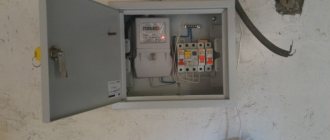
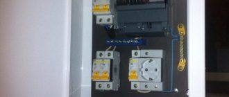
Sooner or later, each of us may face the moment when the time comes to replace the circuit breaker in the electrical panel.
This can happen for various reasons:
- burnt contacts
- the machine stopped holding the load
- frequent false positives, etc.
The most common case is contact burnout.
If your machine starts to knock out, but there are no signs of damage (blackened body or burnt insulation on the wire), first find the reason for its operation and never rush to change the machine to a larger value.
Remember that machines are selected primarily based on the cross-section of the cable connected to them, and only then look at the load.
But if in your case the time has come for replacement, you should know how to do it correctly.
Let's consider two options:
- replacing a circuit breaker with voltage relief
- live replacement
How to replace a machine in a panel
The expression “replacing a circuit breaker with voltage relief” means that not only this switch must be turned off, but all voltage before it must be removed. As a rule, to do this, turn off the input circuit breaker, switch or package that supplies the entire switchboard.
After disconnecting using an indicator screwdriver or a multimeter, you need to check and make sure that there is no voltage on the contacts.
Next, loosen the screw clamps on the switch at the top and bottom.
This can be done with either a Phillips-head or a flat-head screwdriver, since the profile of the screws in modular machines is designed for any of them.
Although professional electricians use a special tool with a Pz/fl or Ph/sl profile for this.
What it is and whether you need it, you can find out in a separate article.
If the contacts were previously heated and melted, then you will not be able to unscrew such a screw.
This happens very often on aluminum wiring. This metal weakens over time and begins to leak. The contact is weakening more and more.
It is said that the new aluminum wires made from alloys 8030 and 8176, which have recently been approved again for use in home wiring, do not have these disadvantages.
However, only repeated practice can confirm or refute these statements. ″[/img]
So, if it is impossible to unscrew the screw, simply cut the wires themselves with side cutters or pliers in a clean place where there is no melting or blackening of the insulation.
You only need to connect the stripped, clean ends of the wire to the new machine. Otherwise, the whole situation will repeat itself again very soon.
Next, take the wires to the side and begin dismantling the switch.
Tools and materials
To replace plugs, you can use different types of input panels. The main thing is that all elements of the reconstructed circuit are installed in them technologically correctly. According to the new requirements, the meter readings must be read without opening the box.
Basic tools and devices for replacing electric meter plugs with circuit breakers:
- indicator;
- wire cutters with dielectric handles;
- a set of screwdrivers with dielectric handles;
- round nose pliers with dielectric handles;
- electric screwdriver with self-tapping screws;
- flashlight;
- insulating tape;
- circuit breaker 10–15 A;
- DIN rail 150 mm;
- "0" - bus;
- PPE caps.
When performing installation work, you may need to extend some wires. Existing standards in electrical engineering prohibit connecting wires using simple twisting. They can be connected using special protective PPE clamps, spring terminal blocks, or welding and soldering methods.
How to remove a machine gun from the rack
Almost all modern modular machines are mounted on a DIN rail. It may differ in size and profile, but the principle of installing any switching devices on it is the same.
Locate the U-shaped eyelet on the bottom of the switch. Insert a small flathead screwdriver into it and pull down.
If you have a two- or three-pole circuit breaker, an RCD or a differential circuit breaker, there may be two such eyes. Each of them will have to be pulled back.
Next, without removing the screwdriver, use it as a lever to make a slight upward movement and release the lower part of the machine from the Din-rail.
Then lift the machine body itself up and completely remove it from the fasteners.
It seems that everything is simple and elementary, but in the cramped conditions of a small switchboard, all these fragile eyes often break. This is not a problem on old switches, but a new one is worth taking care of.
Another caveat is that some of the lugs are spring loaded. Once you pull the screwdriver out of them, they immediately come back.
This is especially inconvenient on two and three-pole models. You have to show miracles of dexterity.
In addition, the above-described dismantling is easily carried out on single machines or devices connected both from above and from below using a regular single-core wire. But there are switches that are located inside the whole assembly, powered through the so-called phase comb.
This is a very convenient and reliable thing that all electricians have been using for a long time. So, if you need to change the machine in exactly this row or chain, you will have to unscrew all the contacts, all the switches where this comb goes.
Then pull it out and only after that dismantle the desired switch. You won't be able to do this any other way.
If you have an old-style machine gun, which is tightly attached with threaded screws directly to the metal base, then the main problem here will be related to unscrewing these same screws.
Over a long period of time they may rust. Therefore, stock up on WD-40 in advance. You may even have to drill them out.
Instead, it is recommended to install already modular instances. To do this, attach a short piece of DIN rail to self-tapping screws, and then install a new switch on it.
Where should the incoming wire go?
Electrical installation rules indicate that power is supplied to a fixed power contact. In other words, the incoming wire must be connected from above, and any practicing electrician will agree with this. It is convenient, understandable and aesthetically pleasing; any master who will work after you will mentally thank you for maintaining the system.
However, be careful! In old houses, distribution boards on the floors have a peculiarity: power to the circuit breakers comes from the lower terminals and is distributed to the apartments above.
Installation of the machine in the panel
Installation of a new modular device is carried out in the reverse order. First, the upper part of the switch sits on the DIN rail.
Then use a screwdriver to pull out the eyelet and press the bottom one. After which the lower grip is released and snaps into place.
All that remains is to connect the contacts. If you previously had stranded conductors crimped with appropriate lugs, then you simply insert them back into the upper and lower terminals and tighten the screws.
If the core was without a tip, then there is a high probability of its deformation, bending, etc.
In this case, if you have a supply of wire, it is better to bite out the old tip and strip it again. After that, use a screwdriver to clamp a fresh, non-deformed conductor.
However, do not overdo the tightening force. On inexpensive modular circuit breakers, the screws come off very easily. “Insufficient contacts” are also dangerous.
Each clamp in such devices must be “pulled” with a certain force calculated by the device manufacturer.
Professionals use special torque screwdrivers for this task.
What other mistakes can await you during such a seemingly simple operation as replacing a machine? The first and most common is when a wire with insulation gets under the clamping contact.
The second is connecting several wires of different sections to one terminal.
Quite often, two wires are connected to the same machine at once. This is mainly used on the upper terminals, where such conductors act as jumpers.
In this case, it is better to use a factory comb or design as in the photo below.
After connecting the wires, apply voltage to the machine by turning on the input switch. Next, you need to check how the new device behaves under load.
Plug electrical appliances into sockets at home and make sure that there are no sparks, crackles, heating or other extraneous effects at the switch contacts. It is best to check heating using a pyrometer.
If you have one, of course.
Minimum requirements for switchboard design
In addition to the importance of preliminary calculations, which we talked about above, when creating a shield diagram, it is necessary to take into account some nuances. In general, they do not require strict implementation, but when introduced into the design, they greatly increase its reliability and ease of use. On the one hand, you need to strive for simplicity of the device, on the other hand, do not neglect the advice of experienced specialists
First of all, this concerns the division of connections into several power lines. In an emergency, this approach allows you to quickly locate the location of the breakdown. An important point with several lines is the possibility of only partial loss of energy supply to the room
On the one hand, you need to strive for simplicity of the device, on the other, do not neglect the advice of experienced specialists. First of all, this concerns the division of connections into several power lines. In an emergency, this approach allows you to quickly locate the location of the breakdown. An important point with several lines is the possibility of only partial loss of energy supply to the room.
This separation rule fully applies to circuit breakers. The optimal connection of machines in the distribution board is carried out according to the following scheme - each room separately. In this case, it is desirable that a separate circuit breaker be installed on the line of lights and sockets.
Panel with digital sensorsSource electrician-electromontazh-kazan.rf
The main connection of the machines in the panel is made through one central switch. Don’t forget about appliances with high energy consumption – cooktops, washing machines and the like. All of them are connected to the network through a separate machine.
Replacing a live circuit breaker
Now let's consider the case when you do not have the opportunity to turn off the voltage, and the burnt out circuit breaker needs to be replaced one way or another.
This may occur due to the absence of an input switch or switch. Or you need to replace it.
Sometimes the packet is replaced with this same switch, which will then play the role of an introductory one.
By the way, in this case, instead of a simple machine, install a load switch. What it is and why it needs to be mounted on the input, read in a separate article.
All this work usually takes place in the entrance. A simplified diagram of a typical floor electrical panel (for one apartment) in most high-rise buildings looks like this.
The so-called riser runs along the side. Four wires with three phases and zero.
From this zero, as a rule, the entire panel housing is also zeroed. In some places, the insulation from the riser cores was removed and special clamps, popularly called “nuts,” were installed.
Through them, phase and zero are supplied to the packet switch (packet).
In houses with major renovations, input switches are already installed instead.
By the way, the package is a rather unsafe thing and very often when switching it is blocked by its metal body.
Therefore, experienced electricians turn such devices on and off by turning away and averting their eyes.
Next, the voltage from the packet goes to the electric meter. After the meter, the zero goes to the clamping block, and the phase goes through the machine to your apartment. There is already a separate switchboard there.
There are usually 3 machines installed in the driveway, but many still only have two (lights + sockets).
Never attempt to replace live circuit breakers in panels that are in unsatisfactory condition.
Even all the advice given below will not help you avoid unpleasant consequences in such switchgears.
Such work is only possible where all switching equipment is securely fastened and there are no poorly insulated twists, splices, etc.
The first thing I would like to note is that if you do not have any experience in working with electricity, never attempt to replace live protection devices yourself. Invite experienced electricians for this task.
The advice will apply primarily to those who already have an idea of this work, and have more than once repaired, assembled panels or changed machines, but without stress.
Remember the main rule - work under voltage should be performed only with a special insulated tool that has been tested up to 1000V and is intended for this type of activity.
No screwdrivers with bare blades or pliers with handles wrapped in electrical tape.
This insulated tool is available in special colors and has corresponding inscriptions.
Secondly, you need to work not with bare hands, but with gloves.
If you have dielectric ones, this is the best option.
At the same time, your feet should also be wearing shoes, and not simple slippers. A dry rubber mat from the bathroom would also be quite appropriate.
Third, all work in an electrical panel is energized, similar to a surgical operation. And as with any operation, a second person must be present next to you. Never do this alone.
What is the difference, advantages and disadvantages
The first thing that needs to be said about the packetizer is that it is a manual device, without automatic operation (snapping off with release of contacts during overloads, short circuit). For on/off chain, you must manually turn its handle with a tight stroke.
It must be said that the design still remains functional, but for housing it has largely lost its relevance. On the other hand, in electrical installations (industry, manufacturing, energy, stations), where the specificity requires the manual principle of activation/deactivation of equipment, the use of packets is widespread and is a standard. In new housing such switches have not been installed for a long time; instead of them - AB. As a rule, replacement is always done if electrical communications are repaired, wiring or panels are updated.
Differences between a packager and a circuit breaker (AB)
Packers are being replaced with automatic switches. As a rule, there is no alternative to automatic machines. ABs are much more modern with autonomous response to overloads, and they can also be controlled manually: move the switch, closing/opening the circuit when needed, that is, the device is much more versatile.
| Characteristic | Switches | |
| Batch | Auto | |
| Functions | Switching only. | Switching and protection against overloads and short-circuit currents. |
| Design | Fully mechanical circuit contact opening/closing design requiring only manual operation. Simply put, the principle of operation of the product is the same as that of ordinary household lighting switches. | It contains two releases:
|
| Control | All control is manual only. | Activation is only manual, and this is logical, since the user must be able to activate the source of danger—the network—himself. Shutdown - both manual and automatic. |
| Installation | To the shield body or to the rail, but usually only with screws. | The DIN bar has a snap-on design, and there are also accessories for screw and other fixations. |
| Possibility of other switching schemes (options) | Yes, variations between terminals are possible. | No, but this is not required in the terms of use. |
Features of differences
The main difference is that the machine has the function of protecting the circuit from short circuits and overloads, and turns itself off in case of danger, while the packet switch is an ordinary mechanical switch, its principle is no different from that. Hand switches are usually round, multifaceted, with a longitudinal handle, and often have a retro design. AB is a flat gray plastic box with yellow, red, blue, etc. colors, small levers (flags) with up/down movement. Older models may be push-button. Such boxes are conveniently placed modularly - they can be simply and easily added in a row on a DIN rail.
With a package switch, if, for example, no one is at home and there is no one to turn the switch, the overload will remain in effect until the wiring completely burns out, and this can cause a fire in the entire building. And with AB there will be automatic release of contacts, disconnection, de-energization at the slightest sign of incorrect operation of the network. The maximum that can happen is that the wiring will overheat a little.
The circuit breaker protects the wiring from heating and melting, fire; the following stages of protection in the form of an automatic shutdown are selected for it and the cross-section of the conductors - RCD, RCBO. The latter and AB can also be installed on the package.
Advantages and disadvantages
The advantages of AV are obvious - automaticity, compactness, ease of installation, circuit protection. Disadvantages of the package: none of the above, and also the switches break due to frequent power surges, the contacts can burn out. AB does not have such a property, since it will simply open the circuit, which will prevent heating of the device.
AV has no disadvantages compared to packagers, except for one exception, but it is due to the specificity of the use environment. In electrical installations, at electricity production and distribution facilities (stations, substations), sometimes a manual switch off/on method is required. and the ability to change contact options - then a manual switch is indispensable.
Fuse selection procedure
To ensure uninterrupted and safe operation of the electrical network, fuses must be selected taking into account the expected operating conditions. To do this, the general power indicators of the operated devices are summed up.
A simple calculation example. In the house it is possible to simultaneously turn on the following electrical appliances with power indicators:
- refrigerator (450 W);
- electric stove (6000 W);
- microwave oven (2000 W);
- TV (180 W);
- washing machine (800 W);
- lighting devices (400 W).
The total value of the electric current is calculated using the formula:
A = ∑Р/U, where:
- A is the desired current value in amperes;
- ∑Р – the total power of electrical appliances, in this case equal to 450 + 6000 + 2000 + 180 + 800 + 400 = 9830 W;
- U – rated voltage value equal to 220 V.
Substituting the numbers into the formula, we get:
A = 9830/220 = 44.68 A.
Circuit breakers are manufactured with different current limit values. The closest standard model in terms of current is rated at 50 A.
Additionally, you will need to check the cross-section of the electrical wiring wires for the total power of electrical appliances in order to eliminate the risk of thermal overheating of the network. The indicator is checked against the table, depending on whether copper or aluminum wiring is used:
In the example given, the cross-section of the wires must be no less than:
- for copper – 6 mm;
- for aluminum – 10 mm.
If it turns out that the cross-section of the wire in the home network is less than specified, it is recommended to change the wiring to eliminate the risk of fire and failure.
It is recommended to purchase circuit breakers instead of outdated plugs. It is advisable to use a two-pole switch that turns off both phases simultaneously. If you install separate switches on the neutral and phase wires, when the contact at zero is disconnected, the phase will remain connected, which is associated with the risk of failure of electrical appliances.
Removing the old circuit breaker
In modern electrical panels, circuit breakers are mounted on DIN rails. The work of replacing them can be done in the shield yourself. Start by disconnecting the wires that connect this protective device to the network. To do this, you need to unscrew the screws that provide the contact connection. If the contacts are burnt and the housing is partially destroyed, performing this operation will require certain experience and skills. After the screws are unscrewed, the wires are pulled out of the contact clamps and taken to the side. If the screws cannot be unscrewed, the wires are “bitten off” using side cutters.
Older houses have devices that are attached with long screws. When dismantling them, a problem may arise - it is difficult or impossible to unscrew the screw, which over time sticks to the wall of the shield due to rust.
Regulatory documents and rules
The requirements for installing an electrical panel are specified in GOST 51321.1-2007. The panel is a switchgear operating under voltage up to 1 kW. Its features are discussed in Chap. 4.1. 7th edition of the PUE. The requirements for the ASU in a residential multi-storey building are specified in GOST 51732-2001, and for switchboards - in GOST R 51628-2000. Since the apartment electrical panel is a low-voltage switchgear and control device, you need to refer to GOST 51321.1-2007.
Basic requirements and installation rules
GOSTs and PUE indicate the correct way to connect the panel.
The standards note several points:
the presence of a complete circuit with the rating of the circuit breaker, the type and cross-section of the cable, installed and one-time power, protection parameters of the housing shell; installation of modules equipped with a nameplate inside or outside is permitted; mandatory affixing of the “Caution Voltage” sign in the form regulated by GOST R 12.4.026; selection of cable cross-section for laying inside according to the rating of the circuit breakers;
selection of wire insulation capable of withstanding an alternating current voltage of at least 660 V; protection of bolted connections from vibrations and short circuits with disc springs, controllers, spring washers, tips; assembly of neutral conductors on N and RE buses; connecting the REN wire to the RE panel; use of terminals to protect input and output wires; performing work using screwdrivers with slots for screw slots, tools with insulated handles; cable marking with colored PVC tubes - blue/light blue (working zero), yellow-green (protection zero), red/brown (phase); marking of N and RE bus contacts according to the serial numbers of protective circuit breakers; connection of one conductor per bus terminal N or RE; designation of outgoing cables with round (line voltage from 1000 V), square (voltage up to 1000 V), triangular (control) tags.
Which case is more reliable - metal or plastic?
Metal distribution panel in a wooden house
The apartment panel is available in metal and plastic casings. The choice of material depends on the project, design specifications and financial capabilities of the user.
The metal electrical panel has a number of features:
- reliable landing on protective zero;
- high anti-vandal characteristics;
- good fire resistance;
- installed on the street or in the entrance;
- moisture resistance class IP31 – IP54.
The disadvantage of a metal case is the need for grounding. The third wire will need to be brought out from the main power supply panel of the apartment.
Plastic electrical panel near the door in the hallway
The plastic case has the following characteristics:
- suitable for interior design;
- can be built into a special niche;
- resistance to wet environments;
- beautiful transparent or tinted door;
- excellent dust resistance.
If the insulation is poor, there is a risk that the plastic will ignite and cause a fire. In this case, it is better to purchase a box made of textolite.
Why is electrical knowledge necessary?
Information about electrical devices known from school physics lessons is not enough for practical use.
The average consumer more often encounters circuit breakers, since they are the ones that trip due to network overloads. It is not enough to simply return the lever to its usual position; you must definitely understand the reasons for the shutdown, otherwise the situation may repeat itself in the near future.
To navigate the electrical panel (which, by the way, is a mandatory element of the energy system of private houses), you need to know the composition and purpose of all devices - pulse relays, load switches, RCDs, etc.
Do you need to be able to change the automation yourself? We recommend that you first study the theory, and at the first shutdown, practice.
The fact is that it is not always possible to get quick help from professionals: on days off, electricians rest like everyone else. And if the house is located in a country house or in a village, it is better to become thoroughly familiar with the electrical network and related devices.
RCD installation instructions
First you need to choose a place to mount the device. There are 2 options: panel or cabinet. The first resembles a metal box without a lid, fixed at a height convenient for maintenance.
The cabinet is equipped with a door that can be locked. Some types of cabinets have openings so that you can take meter readings without specially opening the door and turn off the devices.
Protective devices are fixed on mounting DIN rails located horizontally. The modular design of automatic devices, difavtomats and RCDs allows you to place several pieces on one rail
The neutral wire is always connected to the left terminals at the input and output, and the phase wire to the right terminals. One of the options:
- input terminal N (upper left) – from the input circuit breaker;
- output N (lower left) – to a separate zero bus;
- input terminal L (upper right) – from the input circuit breaker;
- output L (lower right) – to group machines.
By the time the protective device is installed, circuit breakers may already be installed on the panel. To organize the arrangement of devices and wires, you may have to rearrange the devices in a certain order.
We present an example of installing an incoming RCD in an electrical cabinet that already has a meter, an incoming circuit breaker and several circuit breakers for individual circuits - lighting, socket, etc.
Never connect an RCD at the input - it always follows the general input circuit breaker. If a counter is used, the residual current device moves to the third position from the input.
Description of the connection process:
- We install the device on the DIN rail to the right of the machine - just touch it and press with a little force until it clicks;
- we stretch the cut and stripped wires from the machine and the zero bus, insert them into the upper terminals according to the diagram, tighten the fastening screws;
- In the same way, insert the wires into the lower terminals and tighten the screws;
- testing - first turn on the general circuit breaker, then the RCD, press the “Test” button; When pressed, the device should turn off.
To make sure the connection is correct, leakage current is sometimes simulated. Take two working wires - “phase” and “ground”, and simultaneously connect them to the base of the electric lamp. A leak appears and the device should work immediately.

