Is it possible to connect light bulbs in parallel?
This type of connection is the most effective. The lamp is connected to phase and zero. When connecting two or more lamps, the voltage supply wires may become twisted.
But more often all loads are attached to a common cable. Parallel connection can be beam or daisy chain. In the first option, a separate cable is supplied to each lamp. In the second, phase and zero are supplied to the first lighting source, the remaining devices are partially energized.
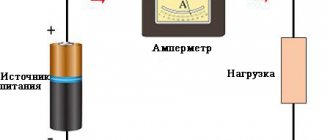
Connecting loads to the network.
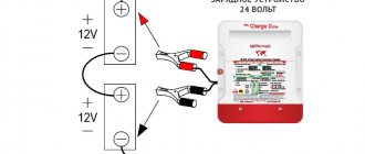
When using halogen lamps with a transformer, you must remember that they are connected to the secondary winding of the converter using terminal blocks.
By parallel connection, you can somewhat smooth out the shortcomings of lighting equipment and reduce the flickering of fluorescent lamps. A capacitor is added to the circuit to shift the phase of all circuit elements.
What's the end result?
If you thoughtfully approach the issue of connection, then such work will not pose any special difficulties. The main thing is not to neglect safety issues when carrying out electrical installation work. It must be remembered that all work is carried out only with the voltage turned off, because 220 volts is a dangerous current, the shock of which can lead to death or serious damage to the body.
If there is even the slightest doubt that self-installation is possible, it is better to seek help from a specialist. After all, if the quality of the connections is poor, the wiring may catch fire and, as a result, a fire in the house or apartment. Therefore, as they say, “measure twice, cut once.”
The article will talk about ways to connect one, two or more light bulbs in one and two-button switches, and consider diagrams that will simplify the progress of work.
CONTENTS (click on the button on the right):
Rules for connecting light bulbs
When connecting lamps, you must follow the rules. Let's look at serial and parallel connections.
Sequential
A serial connection involves connecting to a 220 V network so that the same current flows through all elements in the circuit. In this case, the distribution of voltage drops is proportional to the internal resistance of the loads. Power is also distributed proportionally.
When using a connection in series with a general switch, the lights will not burn at full strength. When connecting lamps of different wattages, the device with higher resistance will have a brighter glow.
The diagram of a standard serial connection is shown in the figure below.
Serial connection diagram.
Parallel
It is distinguished by the supply of full mains voltage to each lamp. The current will vary depending on the resistance of the device.
Parallel connection diagram.
The conductors are connected to the lamp sockets in the same way, sometimes according to the bus principle, when all loads are connected to a common line.
You can connect as many light bulbs as you like to one supply. The switch operates in the same way as when connected in series.
Disadvantages of the scheme
In addition to the significant voltage drop, the second negative aspect of such a circuit is its unreliability.
If only one light bulb in this circuit burns out, all the others will go out immediately.
It should also be noted that such a series circuit is well suited for conventional incandescent lamps. On some other types, including LED ones, you should not expect any effects.
They may have in their design an electronic circuit that requires a power supply of about 220V. Of course, they can operate from small values of 150-160 V, but 90 V or less will not be enough for them.
Pros and cons of parallel connection
Pros:
- if one element fails, the rest will continue to work;
- the circuit gives the brightest light possible, since full voltage is supplied to each device;
- You can remove as many wires as you like from one lamp to connect additional loads (you will need one zero and a specific number of phases);
- Suitable for energy-saving electrical devices.
Connection diagram of an energy-saving lamp to electronic ballasts.
There are practically no disadvantages, except for the large number of conductors in a branched system with many lamps.
Compliance with safety rules when connecting a chandelier
Working with live parts always involves a certain amount of risk. Connecting a chandelier to a home is no exception, and the work is done at height. To protect yourself and others during electrical installation work, you must follow the following safety rules:
- Carefully study the instructions for connecting the chandelier.
- The power tools used in the work must be in good working order, especially with regard to the insulating parts of the tools.
- Equipment for climbing to heights - stepladders and other devices - check for reliability and stability of the structure.
- Before starting work, stop the power supply by turning off the circuit breakers in the electrical panel.
Application
In everyday life, parallel connections are very common. For example, Christmas tree garlands, where all the light bulbs have maximum brightness.
By connecting, you can create interior lighting of any length. Replacing a burnt out element is easy. Two 60 W devices can be exchanged for one 10 W lamp without compromising the lighting parameters. This property of the circuit is used by experienced electricians to identify the phase in three-phase networks.
Halogen lamps and incandescent lamps not only produce a bright glow, but also heat the environment. For this reason, they are often used in garages, hangars or workshops for heating rooms. To do this, connect the devices to the network, placing them in a metal block. The design heats up to 60 degrees and maintains a comfortable room temperature. However, high powers lead to frequent lamp burnouts.
Related video: WHAT IS SERIAL AND PARALLEL CONNECTION
Parallel connection is used in strip lighting, chandeliers, and street lighting. Each lamp can be controlled separately, which increases the convenience of using the overall network. You just need to install the required number of switches into the system.
In houses and apartments, not only lighting devices, but also various equipment are connected to the network in parallel.
When creating lighting devices with LED elements, a mixed connection is often used based on a series circuit of loads, followed by a parallel connection to the same circuit.
We recommend watching: How to understand whether to connect lamps or loads in series or parallel
Preparatory work
No matter how many keys your switch has (one, two or three), the preparatory work will be the same.
To begin with, you need to install a general distribution box and a mounting box for the switching device in the room; it is also called a socket box:
- If the walls in your room are made of PVC, plasterboard sheets, wood or MDF panels, install a special bit with serrated edges on a drill and make a hole. Insert the mounting box into it and fix it to the wall using self-tapping screws.
- For concrete or brick walls, make a hole using a hammer drill or drill with an attachment that works on concrete surfaces. But in this case, the mounting boxes must also be fixed using gypsum or alabaster mortar
As a rule, the installation of holes is carried out simultaneously with the laying of grooves. This is done purely for aesthetic reasons; there is a lot of dirt from such construction work, and it’s better to spray it once and clean it up. Grooves are grooves in the wall surface into which connecting wires will then be laid. They can be done using various tools:
- Hammer and chisel. This is an old ancestral method, its advantage is the complete absence of costs for purchasing tools (every man has a hammer and chisel). The disadvantage of this method of gating is that it takes a lot of time and effort.
- Bulgarian. This tool is often called the worst of the best. It’s convenient that grooves can be made quickly and without much effort. But it is from the grinder that there is a lot of noise and dust, and besides, it is not possible to make grooves of the same depth along the entire length, and it is almost impossible to work with the grinder in the corners of the room. So choose such a power tool as a last resort.
- Hammer. All you need is to purchase a special attachment for it - a strober or a spatula. In all other respects there are no shortcomings, it’s fast, convenient, the grooves are more or less even.
- Wall chaser. This is the ideal tool for this type of work. Works efficiently, safely and quickly. The grooves are smooth, there is no dust, since the wall chaser is connected to a construction vacuum cleaner. They are comfortable to work with and the tool does not make much noise. The only drawback is the high price. But there are services where you can rent a wall chaser.
Read also: Denominations of introductory machines table
Briefly about gating walls using the tools listed above is described in this video:
It is necessary to lay two-core wires into the grooves and fix them with cement or alabaster mortar.
So, the preparatory work is completed, the boxes are mounted, the wires are laid, and you can connect the light bulbs and switch.
An example of calculating the connection of lamps of different power
To understand the differences, it is enough to know Ohm's law and other simple electrical laws.
Let there be an incandescent light bulb with a voltage of 220 volts. At a frequency of 50 Hz, it represents a purely active resistance, so it is more convenient to understand initial questions with it. If the lamp has a power of 100 watts, then when connected to the network, a current I=P/U=100 watts/220 volts=0.5 A (approximately enough for reasoning). The full network voltage of 220 volts will drop across it. You can calculate the resistance of the thread: R=U/I=220 volts /0.5 amperes =400 Ohms (approximately).
If you connect a second similar light bulb in parallel with the first, then it is obvious that the entire mains voltage will be applied to each lamp. The current consumption Ipot will branch into two streams and current I=U/R=220 volts/400 Ohm=0.5 amperes . The current consumed will be equal to the sum of the two currents (as Kirchhoff's first law says) and will be 1 A. As a result, both lamps will be under full mains voltage, the rated current will flow through them, and the total luminous flux will be equal to twice the flux of one lamp.
Parallel and series connection of light sources of equal power.
If two identical lamps are connected in series, the mains voltage will be divided between them, and each will drop about 110 volts. The total resistance of the circuit will become equal to Rtot = 400 + 400 = 800 Ohm , and the current through each lamp (with a series connection it is the same for each element) will be / 800 Ohm = 0.25 A. The result is:
- only half of the mains voltage drops on each lamp;
- a current flows through each lamp, reduced by 2 times from the rated one.
To estimate the luminous flux of incandescent lamps for a given case, you can use the Joule-Lenz law. Incandescent lamps glow by heating the filament. Over a period of time t, the thread will release the amount of heat Q=I2*R*t=U*I*t . The current will be halved, the voltage on one lamp will also be halved. This means we can expect a decrease in luminous flux by 2*2=4 times . For two lamps, the flux will decrease by half relative to one lamp in nominal mode. That is, when connected in series, two light bulbs will shine approximately twice as dim as one.
The problem can be solved by using lamps with an operating voltage two times lower than the mains voltage . If you use two hundred-watt light sources with a voltage of 127 volts, then 220 volts will be divided in half, and each lamp will operate in nominal mode, the luminous flux will double compared to one lamp of the same power. But this does not get rid of the main drawback of such a circuit - when one lighting fixture fails, the circuit breaks, and the second lamp also stops shining.
All of the above applies to lamps with the same power. If the power of the lamps differs markedly, then the following effects occur in the circuits. Let one 220-volt lamp have a power of 70 watts, the other 140.
Then the rated current of the first is I1=P/U=70/220=0.3 amperes (rounded), the second is I2=140/220=0.7 amperes . The filament resistance of the less powerful lamp is R1=U/I=220/0.3=700 ohms , the second - R2=220/0.7=300 ohms .
A lamp with a higher power corresponds to a lower filament resistance.
Parallel and series connection of light sources of various powers.
With a parallel connection, the voltage on both devices will be equal, and each lamp will have its own current. The total current consumption is equal to the sum of two currents Ipotr = 0.3 + 0.7 = 1 ampere. Each lamp operates in nominal mode and consumes its own current.
In a series connection, the current will be limited by the resistance Rtotal = 300 + 700 = 1000 Ohms and will be equal to I = U/R = 220/1000 = 0.2 A. The voltage will be distributed proportionally to the thread resistance (power). On a 140 watt lamp it will be 1/3 of 220 volts - approximately 70 volts. On a low-power lamp - 2/3 of 220 volts. That is, about 140 volts. Both lamps will shine at a low level due to a decrease in voltage and current, but the mode for them will be light. It’s another matter if lamps at half the mains voltage are used. On a lamp of lower power, the voltage will be higher than permissible, and the greater the difference in power, the greater the difference. This lamp will soon fail. And this is another disadvantage of connecting lamps in series. Therefore, such a connection is used extremely rarely in practice. An exception is the series connection of fluorescent lamps. It is believed that with this scheme they work more steadily.
Series connection of fluorescent light sources. The starters here are also rated at 127 volts.
To summarize the differences between parallel and serial connection:
- when connected in parallel, the voltage on all consumers is the same, the current is distributed in proportion to the power of the lamps (if the power is the same, then the currents will be equal), the total current consumption is equal to the sum of the currents of all lamps;
- with a series connection, the current through all lamps will be the same, it is determined by the total resistance of the circuit (and will be less than the current of the lowest-power lamp), the voltage across consumers will be distributed in proportion to the power of the lamps (if it is the same, then the voltages will be equal).
Using these principles, you can analyze the operation of any circuit.
Switch device
Before connecting two light bulbs to one switch, let's take a closer look at the design of this switching device. It is not complicated, and once you understand the design, you can easily deal with the connection diagram later.
The main component of the entire mechanism is the working part, which is directly installed in the socket box. It looks like a metal structure; a drive is attached to it, with the help of which the device is turned on and off. If we consider in detail, the drive, in fact, is a moving contact, which, changing its position, closes or opens a circuit between two fixed contacts.
One of these fixed contacts is called incoming and must be connected to the phase wire from the supply network. The second contact is called outgoing, it is connected to the phase wire going to the light bulbs. If the switch is in the correct position, these two fixed contacts must be open to each other, the device is considered to be turned off, there is no circuit between the power supply and the lamp, and the light bulb does not light. As soon as you press the switch button, the movable contact closes two fixed contacts with each other, through the formed closed circuit from the supply network, voltage is supplied to the lamp, and the lamp lights up.
For safety, the working part of the switch is placed in a housing made of dielectric material (porcelain or plastic).
The second component of the switches is protection, this is the frame and keys, usually they are made of plastic. The key is attached to the drive of the working part, with its help a person presses, thereby changing the position of the moving contact, and thus controls the lighting. The frame serves as protection against accidental human contact with the live contact part of the switch. It covers and isolates it all, that is, there is no possibility of touching the working parts. The frame is secured with plastic latches or screws.
The only difference between a 2-key switch is that it has two output contacts. Each of them must be connected to the phase wire of one of the two light bulbs.
How to avoid mistakes
Electrical appliances must be connected to the network in compliance with electrical regulations. The connection features are not obvious and may be incomprehensible to people far from the topic.
It is important to consider:
- Each type of connection has features associated with Ohm's law. In a series connection, the current is equal in all parts of the circuit, while the voltage depends on the resistance. In a parallel connection, the voltage is the same, and the total current is the sum of the values of the individual sections.
- Any circuit should not be overloaded, as this can lead to unstable operation of the devices and damage to the conductors.
- In a parallel connection, the cross-section of the wires must correspond to the applied load, otherwise overheating of the conductors is inevitable, followed by melting of the winding and a short circuit.
- A phase is supplied to the switch, zero goes to the lighting fixture. Failure to comply with this rule may result in electric shock when replacing the lamp, since even when the device is turned off, the device is energized.
- The main wire from the lamp is connected to the common contact. If you connect it to a tap, only part of the circuit will work.
- Before installing the switch, it is better to mark the wires in advance. During installation, it will be easy to connect the same conductors together.
Failure to follow the recommendations may result in unstable operation of lighting equipment, rapid lamp burnout, and serious injury that could lead to life-threatening injuries.
Connecting one lamp to a single-key model
Let us describe a method for connecting a light bulb to a switch with one control button. Some types of symbols indicated on the device:
- if number 1 is marked, this is an input phase contact, number three is marked as an outgoing phase contact;
- letter designation L - incoming phase contact, number 1 - outgoing phase;
- L – input, arrow – exit.
The following tools will be useful during the work process:
- knife to scrape insulation from wires;
- screwdrivers with insulated handles: indicator and Phillips;
- marker;
- insulating tape.
Instructions:
- Turn off the electricity at the machine or panel.
- The switch is mounted where the phase break was provided. The “zero” wire goes to the light bulb.
- Strip the insulation from the wires. The ends should be trimmed 8-10 mm on each side.
- We connect the phase to the input contact of the switch. With the standard location of the switch, the input terminal should be located at the bottom.
- We conduct the phase from the lighting fixtures to the outgoing contact terminals.
- Press the wire to the contact, tighten the screws. The core should move 1-2 mm away from the contact.
- The phase from the distribution box is connected to the phase contact of the switch.
- We run wires from the switch to the lamp. We take the zero directly from the switchboard to the rim of the base. The phase passes through the switch and is connected to the central contact of the light bulb.
- Insulation of twisted wires.
- Starting the machine.
- Checking the system's functionality.
Under no circumstances should the switch be connected to zero. The load on the device will increase too much. This will lead to rapid burnout of contacts.
By installing the switch on a phase, the supply of current to the end user can be quickly interrupted. This is relevant in case of emergencies. Setting the switch to “zero” will not give the desired result in emergency conditions. Disabling in this case will only open the circuit, but will not lead to de-energization of the entire system.
Combined triple instruments
Switch with built-in socket
The triple switch, combined with a socket, is a combined version. It is suitable only for installation in certain places where it will be convenient to control the lamp and use the socket. The most suitable place for this is a dressing table in the bathroom, equipped if you need to connect a hairdryer or curling iron while simultaneously turning on the lighting.
You can install and connect such a module in its usual place – on the wall.
However, in this case the provisions of the current standards are violated. According to the PUE, the height of the switches must correspond to the level of a person’s forearm. The same requirements stipulate that the outlet should be located at a level of no more than one meter from the floor. The inconveniences of such an arrangement also include difficulties in including it in the existing wiring. To connect the combined device, you will need to modify the wiring diagram or run separate wires to it, which is not entirely aesthetically pleasing.
Selection of conductor cross-section
The cross-section of the cable cores depends on the load and installation method. Many years of experience show that a cross-section of 1.5 sq. mm in terms of throughput and mechanical strength is sufficient for 99+ percent of lighting tasks. This size has become a definite standard. The wide distribution of LED products only confirms this thesis - the loads in lighting networks do not increase. But if the case is non-standard, you can select a cable according to the table.
| Conductor cross-section, sq. mm | Allowable current, A | Permissible load at 220 V, W | ||
| Copper | Aluminum | Copper | Aluminum | |
| 1,5 | 19 | — | 4100 | — |
| 2,5 | 27 | 21 | 5900 | 4600 |
| 4 | 38 | 29 | 8300 | 6300 |
| 6 | 50 | 38 | 11000 | 8300 |
Although the rules allow the use of aluminum conductors, it is strongly recommended to use only copper products.
Next, you need to carry out the wiring - lay the cable products in accordance with the selected diagram between all the elements. It is better to use products with conductors numbered and marked by insulation color. If there is no such cable, you will have to perform conductor testing and core marking yourself. The cables should have a small margin of 10-15 cm in length. Upon completion of this work, you can begin the actual installation.