Design features of the W-shaped transformer plate
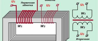
Any transformer contains two main parts: a closed core and copper windings. The core, in turn, consists of plates, which are created using special electrical steel. The thickness of the core plates directly affects the operating frequency of the transformer: the thinner the part, the greater the parameter.
A transformer with an W-shaped core is also called an armored one. The main conditions under which such plates are used:
- frequency no more than 8 kHz;
- maximum power 150V*A.
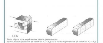
The W-shaped plate increases the leakage flux due to bifurcation of the magnetic flux. The position of the windings on the middle rod of the core protects them from interference and mechanical stress.
Parts for high-frequency transformers are preferably made from three main materials: permalloy, alsifer and ferrite. The latter has a wide range of working particles, which explains the use of ferrite to create pulse transformers.
The description of the transformer magnetic circuit gives the parameters of the set of plates. For example, if it is indicated that it is necessary to take iron Ш15Х10, this means that:
- The width of the middle part of the plate should be 15 mm.
- The thickness of the resulting stack of W-shaped plates is 10 mm.
The main advantage of a core assembled from plates is its resistance to mechanical stress. This allows you to assemble a magnetic circuit even from fragile materials. The disadvantage of the design is increased sensitivity to low-frequency magnetic fields.
When assembling the core, jumpers are added to the W-shaped plate.
To minimize the gap formed between the jumper and the plate, the magnetic circuit is assembled “over the roof”.
MAIN TECHNICAL CHARACTERISTICS
Main characteristics of the transformer:
- input voltage;
- output voltage values;
- power;
- no-load voltage and current.
The ratio of the voltages on the primary and secondary windings is the transformation ratio. It depends only on the ratio of the number of turns in the windings and remains constant in any operating mode.
The power of the transformer depends on the cross-section of the core and the diameter of the wires in the windings (accordingly, the permissible current). The power from the primary winding is always equal to the sum of the secondary powers minus the losses in the windings and core.
Open circuit voltage is the voltage across the secondary windings without load. The difference between it and the voltage under load characterizes the losses in the windings due to the wire resistance. Thus, the thicker the conductors in the windings, the lower the losses and the smaller the voltage difference.
The amount of no-load current depends mainly on the quality of the core. In an ideal transformer, the current passing through the primary winding creates an alternating magnetic field in the core, which, in turn, due to magnetic induction, creates an emf in the opposite direction.
The induced EMF compensates for the applied voltage and TCH is equal to zero. In real conditions, due to losses in the core, the EMF value is always less than the primary voltage, as a result of which TCH occurs. To reduce the current, a high-quality material is needed to make the core; there must be no non-magnetic gap between the plates.
The last requirement is met to the maximum extent by toroidal cores - there is no non-magnetic gap in them.
In what cases is gluing necessary?
Experts note two signs that the W-shaped plates have delaminated and require rewinding and gluing:
- noticeable heating of the primary winding;
- the appearance of a hum.
There is a physical explanation for the incomprehensible noise and temperature rise in the transformer.
As mentioned above, the magnetic circuit consists of plates, each of which has ferromagnetic properties. When electric current flows through the primary winding, a magnetic field is formed around it, which contributes to the generation of energy in the secondary winding. With a constant current frequency, the voltage can rise or fall.
Changes in voltage affect the air surrounding the transformer: vibrations and sound waves arise in it. Having a certain frequency, some of them are accessible to the human ear. But, for example, in pulse transformers the hum is not heard.
The power transformer is more common. If the device used to make a quiet hum, but now it hums noticeably louder, the problem lies in the delaminated plates. If the device not only buzzes a lot, but also heats up, it means that the current load is increased.
Ways to reduce inrush currents
Let's look at what should be done to reduce starting throws. There are several options:
- Connecting a transformer with reduced induction. Such a power characteristic significantly makes the device heavier and increases its cost. The starting current, when the transformer is turned on, will drop to a value equal to the rated current value or lower without connecting an active load, if the induction is half the rated value.
- Supplying voltage to the windings during the period when it is highest. The effectiveness of this action is achieved by using additional connecting devices.
- An active resistance is connected in series with the primary winding of the converter. This option has a minus - overheating of the resistance, which leads to a decrease in efficiency.
If you use a resistance with an inverse temperature coefficient, the efficiency will be higher. This is due to the fact that the thermistor tends to lower its resistance when heated.
Energy specialists know that the so-called packets of the ESB and ESBH series have now begun to be offered on the market with maximum parameters (amperes), 10 and 16, respectively. The operation of these devices involves connecting a voltage-limiting resistance in series with the load. The parameter of this semiconductor is usually 5 ohms. In the described case, the resistance is closed by contact breakers with operation from 20 to 50 ms.
When connecting the converter to the power line, protection elements (automatic circuit breakers) are used. The standards to which the tripping characteristics must comply are: IEC/IEC 898 (tripping D) and DIN VDE 0660 (tripping K). Interrupting elements with the specified parameters are produced for electric motors and transformers. That is, for devices with a large multiple of the starting current to the rated value. Switches D have a multiple of 15, for circuit breakers K this parameter is 10.
What to do if you need to connect a transformer, but there are no protection elements with the specified characteristics? In this case, take the most common switches, which are marked B, C. Remember that such elements must be provided with a two- or three-fold voltage reserve. The machine will work if the force of the starting throw exceeds the nominal parameter by 2 - 3 times, that is, the main protection function will be significantly reduced.
Core gluing technology
When the problem is identified, care must be taken to restore the core. The design does not always require gluing. Noise is often the result of improper assembly, and delamination can be eliminated by tightening them tightly.
If gluing is still necessary, the following instructions will help:
- Calculate the operating current of the primary winding.
- Carefully clean the cores.
- Coat them with a small amount of glue.
- Assemble the transformer.
- Connect the primary winding to a current source.
- Leave until the glue hardens.
Let's look at each step in detail.
Experts advise passing current to magnetize the core plates and heat them. This way the halves of the magnetic circuit will be pressed closer to each other. In order to understand what voltage is needed, you need to make simple calculations. Having measured the resistance of the primary winding (R), calculate the strength of the primary current using the formula I = 220/P. Therefore, the appropriate voltage is U=IR, but more can be used.
The cores must be cleaned as carefully as possible. Hand sanding will cause the core to lose flatness.
Next, the cores are coated with glue and the transformer is assembled. It is important to ensure that the core halves are not mixed up. It is advisable to mark them in advance.
Having connected the windings to the current source, all that remains is to wait for the glue to harden. The process will noticeably speed up the heating produced by the current.
Some craftsmen advise mixing epoxy glue with ferrite powder. The problem is that it is difficult to get. You can make it from a piece of unnecessary ferrite by sharpening it. The purity and structure of the powder are more important. If large particles get into the adhesive mass, this will ruin the adhesion between the plates.
Formula for calculating the starting throw
As we have already found out, to protect the transformer switching line, it is necessary to connect a switch with the appropriate characteristic. To choose the right machine, you need to calculate the starting current of the transformer. To do this, you will need technical documentation for the device. Write down the data from there:
- power (Pn) rated;
- voltage (UH) nominal;
- efficiency;
- power factor cos φH:
- multiplicity of direct current in relation to the nominal value of Kp.
To calculate the rated value of a three-phase device, the formula is used:
- In = 1000Pn / (UH x cosφH x √efficiency), A.
The next step is to determine the size of the starting throw. We calculate using the following formula:
- IP = IH x Kp, A, where
IH – previously determined nominal value;
Кп – direct current multiple to the rated value.
After the calculations have been made, select the appropriate switch according to the parameters.
How to choose glue to seal
For gluing the plates, a universal product based on epoxy resin is used. Epoxy glue is widely used not only in everyday life, but also in industry. The substance gained popularity for its high quality of adhesion between materials of different origins.
Glue is a synthetic product. The composition, in addition to the main ingredient, contains solvents, hardeners and other additives that affect the quality of the product.
Pros of epoxy glue:
- elasticity that prevents the seam from tearing with small shifts;
- crack resistance;
- high degree of adhesion (the composition glues different materials);
When choosing an adhesive for working with a transformer core, you need to remember two types of epoxy resin. Adhesive can be structural or decorative. Decorative is intended for household needs; its seams are neat and transparent.
Structural epoxy adhesives have more powerful adhesion properties. For gluing W-shaped plates, you should use KER-828 and ED-20. Both compositions are resistant to temperature changes and chemical influences and are highly durable.
There are a few minor differences between these brands. Thus, Russian-made ED-20 glue turns yellow under ultraviolet rays. At the same time, the resin is much harder than its analogue and is not erased by hard materials.
KER-828 is a Korean brand and has a lower viscosity. It practically does not turn yellow over time, but is vulnerable to abrasives. However, this small disadvantage does not appear in the operation of glued objects.
Sometimes glue is sold in two tubes and is called two-component. One tube contains liquid epoxy resin, the other contains a thick substance resembling plasticine. To work, you need to mix the contents of both tubes.
If the transformer core, consisting of W-shaped plates, makes unusual sounds and heats up, the problem is delamination. Sometimes it is enough to use zip ties to restore the integrity of the magnetic circuit. In other situations, epoxy resin will help. Follow the instructions carefully and buy high-quality glue.
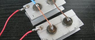
Example of work
There are examples on the Internet of the work of people who were faced with the problem of delamination of core plates. The photo shows the already coupled plates.
If the transformer core, consisting of W-shaped plates, makes unusual sounds and heats up, the problem is delamination. Sometimes it is enough to use zip ties to restore the integrity of the magnetic circuit. In other situations, epoxy resin will help. Follow the instructions carefully and buy high-quality glue.