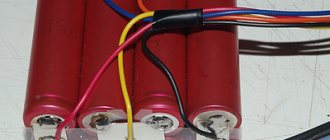
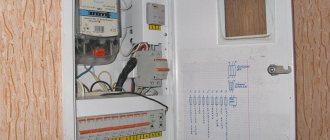
Series connected batteries
For batteries connected in series, the voltage increases, but the capacity remains the same.
Two 12-volt batteries connected in series are charged with a 24-volt charger
When connected in series, the batteries must be of the same type and age. The capacity and manufacturer must also be the same. If one of the batteries has been used before, then most likely its capacity is already less than nominal and during charging it will be charged first. But the charger may not “notice” this and will try to fully charge the remaining ones. The temperature and pressure in the old battery case will increase. Gas will begin to be released, and the active material of the plates will begin to deteriorate.
Under load, the wear of the old battery will increase. After the weak cells have used up their charge, the good ones will continue to produce current. The voltage across the discharged cells will drop to zero, and then their polarity will reverse (this most often happens in large batteries). An uncontrollable increase in pressure and temperature will follow and a catastrophe will occur.
It is recommended to replace the entire battery of batteries connected in series. If you change only one, the state of charge of all batteries should remain the same. The small difference will be eliminated by the charger during the absorption phase. If the differences are large, the more highly charged battery will be recharged, and the undercharged battery will begin to sulfate.
Two 12-volt batteries connected in series are charged with a 24-volt charger. Three - 36-volt.
Connection Precautions
- follow safety rules when working with electric current, wear rubber gloves;
- prevent the creation of a circuit of electric current passing through the human body;
- avoid short circuits;
- do not neglect polarity;
- do not touch the battery terminals with bare hands;
- do not collect batteries connected to loads (check each one separately before connecting it to the circuit);
- the charger must be disconnected before connecting the battery;
- use tools with insulated handles;
- do not neglect the battery current and load parameters before using the unit;
- connecting contacts must be reliable and insulated;
- protect the assembly with an insulating casing from moisture;
- use identical batteries in terms of parameters and degree of wear;
- Before using the assembly, test it for incorrect terminal connections.
When correcting errors, the load (charger) is initially disconnected, then only the unit is remade.
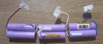
Parallel connected batteries
Parallel connected 12-volt batteries are charged with a 12-volt charger.
When connecting batteries in parallel, the capacity increases, but the voltage does not change. The batteries in the battery should be of the same type and age, and the cables connecting them should be short and thick to reduce voltage drop.
Several 12-volt batteries connected in parallel are charged with a 12-volt charger. The battery charging time will be longer than for a separate battery.
Why are there restrictions?
So, for the successful occurrence of the necessary electrochemical reaction, it is necessary to provide it with a high-quality electrolyte
It is also important to carry out the process in the upper layers and remove the products. The active mass of the battery plates helps with this significantly.
After all, thanks to it it is easier to supply and remove the substance involved in the reaction. But as the “resource materials” move down, things start to happen more slowly. The fact that sulfur appears in the electrolyte also has an active effect. Therefore, connecting batteries in parallel is preferable only when the battery is charged. The lower the actual voltage, the more dangerous the operation of power supplies of different capacities. Therefore, it is desirable to ensure timely nutrition. It would be best not to let the capacity drop below 1/3 of the nominal value.
Chargers with multiple outputs
To simultaneously charge several batteries from a 220 V network, chargers with two or three outputs are used. If it is necessary to connect a larger number of battery groups, install one of the previously listed decoupling devices.
For example, to charge four batteries, you will need one charger with three outputs and one decoupling relay or charging separator.
Examples of chargers with multiple outputs:
- Ultra Light charger
- 30 Amps
- Charging profiles for Gel, AGM, liquid acid and LiFePO4 batteries. Power supply and half power mode. Login for BMS
- Two outputs Each charger output is capable of carrying maximum current. The total current does not exceed 30 A
ORDER
2 year warranty
- Ultra charger
- 60 Amps
- Marine charger. Efficiency > 90%. Three exits. 12 charging profiles. Gel, AGM, liquid-electrolyte, LiFePO4.
- Temperature sensor included The device reduces the charging voltage if the battery temperature exceeds 20 C
ORDER
5 year warranty
- PS1255 charger
- 10 Amps
- Waterproof charger. Two exits. Current 10 A
- Suitable for one or two independent or series connected batteries Charging current varies from 0 to 10 A per channel
ORDER
2 year warranty
Connection Precautions
With all methods of connecting batteries, a number of precautions must be observed:
- observe safety precautions for the operation of electrical installations to prevent electric shock (the main thing is not to create a circuit for the passage of current through the human body):
- observe the polarity of the connection;
- do not create short circuits;
- when assembling batteries, disconnect the load from them;
- connect the charger to the battery when it is disconnected from the network;
- carry out work in appropriate insulating clothing and shoes, without metal objects that could fall and short circuit the contacts;
- do not touch the battery terminals with your hands, especially with both hands on different poles (this is very dangerous on powerful high-voltage batteries);
- use a special tool with insulated parts;
- do not carry out work if you are in poor health;
- take into account the currents passing through the combined battery and the load and use conductors of suitable cross-section;
- when connecting elements into one battery, ensure reliable contact isolated from external influences;
- provide reliable protection of prefabricated batteries from short circuits and moisture;
- use batteries with the same characteristics and degree of wear;
- Carefully check the assembled battery for switching errors.
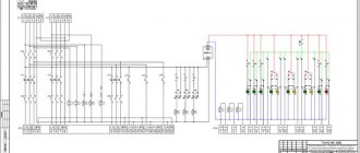
Selection and installation of equipment
Connection diagram of three battery groups to one charging source.
A battery separator and a DC-DC charger are used, providing four-stage charging of service and additional batteries. If the electrical system consists of starting and service batteries of small capacity, and the charging speed is not critical, use an decoupling relay. For complex systems with multiple subsystems, different operating voltages and powerful charging devices, a battery controller and DC-DC chargers are suitable.
Device rating and cable cross-section
The current consumed by a severely discharged battery reaches 100% of its capacity and, in a large service battery, can exceed the capabilities of the generator. In this case, the charged starting battery will try to equalize its voltage with the service one and will also become a source of current for it. Therefore, the cable and the decoupling devices themselves must be designed for this.
All cables coming from the separation system must be of the same size, cross-section and as short as possible. The same goes for the cables running from the negative terminal of the batteries to the bus and connecting the batteries in the battery. All batteries must be the same type, size, age and discharged equally
Protection devices
The cables coming from the batteries must be protected. To do this, install a fuse or circuit breaker as close as possible to the positive terminal of the battery. Only the cable section from the terminal to the fuse remains unprotected, and the risk of fire from an accidental short circuit is reduced.
An additional safety feature is a main switch that completely disconnects the batteries from the charging source.
Force connection
Separate charging systems separate the starting and service batteries when the engine is not running. But if the starting battery is dead and the engine cannot be started, the batteries must be connected intentionally. Some models of decoupling relays have this capability. However, a large starting current can weld the contacts together and damage the relay. To prevent this from happening, a shunt switch is installed parallel to the decoupling relay and used for emergency engine starting.
Ask a question,
and get advice on outboard electric motors, batteries or chargers for a boat or yacht
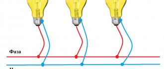
Theory
To connect batteries in series, usually the positive terminal of the first battery in series is connected to the positive terminal of the electrical circuit.
The positive terminal of the second battery is connected to its negative terminal, etc. The negative terminal of the last battery is connected to the negative terminal of the unit. The resulting battery in series connection has the same capacity as a single battery, and the voltage of such a battery is equal to the sum of the voltages of the batteries included in it. This means that if the batteries have the same voltage, then the battery voltage is equal to the voltage of one battery multiplied by the number of batteries in the battery. The energy accumulated in the battery is equal to the sum of the energies of the individual batteries (the product of the energies of the individual batteries, if the batteries are the same), regardless of whether the batteries are connected in parallel or in series.
Lithium-ion batteries cannot simply be connected to a power supply unit - the charging currents on each element (bank) must be equalized. Balancing is carried out when charging the battery, when there is a lot of energy and it can not be saved much, and therefore, without any significant losses, you can use the passive dissipation of “excess” electricity.
Nickel-cadmium batteries do not require additional systems, since each link, when its maximum charge voltage is reached, stops receiving energy. Signs of a Ni-Cd being fully charged are an increase in voltage to a certain value, and then a drop of several tens of millivolts, and an increase in temperature - so that the excess energy immediately turns into heat.
The opposite is true for lithium batteries. Discharge to low voltages causes degradation of the chemistry and irreversible damage to the element, with an increase in internal resistance. In general, they are not protected from overcharging, and you can waste a lot of extra energy, thereby dramatically reducing their service life.
If we connect several lithium cells in a row and feed them through clamps at both ends of the block, then we cannot control the charge of individual cells. It is enough that one of them will have a slightly higher resistance or a slightly lower capacitance, and this link will reach a charge voltage of 4.2 V much faster, while the rest will still have 4.1 V. And when the voltage of the entire package reaches charge voltage, it may be that these weak links are charged to 4.3 Volts or even more. With each such cycle, the parameters will deteriorate. In addition, Li-Ion is unstable and, if overloaded, can reach high temperatures and, consequently, explode.
Most often, a device called a “balancer” is installed at the output of the charging voltage source. The simplest type of balancer is a voltage limiter. It is a comparator that compares the voltage on a Li-Ion bank with a threshold value of 4.20 V. Upon reaching this value, a powerful transistor switch is opened, connected in parallel to the element, passing most of the charge current through itself and converting the energy into heat. In this case, the can itself receives an extremely small part of the current, which practically stops its charge, allowing its neighbors to recharge. The voltage equalization on the battery cells with such a balancer occurs only at the end of the charge when the elements reach a threshold value.
Diode insulator
Diode isolator is a common method of charging two or more batteries simultaneously. The output current of the generator is supplied to diodes, which allow it to pass in only one direction and block its flow between the batteries.
Each battery is assigned its own diode, with which any number of batteries can be charged simultaneously. During operation, the batteries are isolated from each other and the on-board equipment cannot accidentally discharge the starting battery.
Although diode isolators appear to be ideal devices for charging two batteries, they have a significant drawback that is often overlooked. Problems when using battery diode isolator
Diagram 1 - Voltage on additional batteries is 12.8 volts. They will never charge. Scheme 2 - An external regulator increases the generator voltage. The voltage on the starting battery is 15.2 Volts. It's recharging. The voltage on the additional batteries is 14.2 V. They are undercharged. Scheme 3 - The external regulator increased the generator voltage even more. The starter battery will boil
Problems when using a battery diode insulator. Diagram 1 - Voltage on additional batteries is 12.8 volts. They will never charge. Scheme 2 - An external regulator increases the generator voltage. The voltage on the starting battery is 15.2 Volts. It's recharging. The voltage on the additional batteries is 14.2 V. They are undercharged. Scheme 3 - The external regulator increased the generator voltage even more. The starter battery will boil.
A diode can be compared to a valve installed in a water pipe. If the valve is held closed by a spring, then in order to open it, the water pressure must overcome the force of the spring. To open the diode, it is also necessary to perform additional work, which leads to a voltage drop between its input and output.
Depending on the type of diode and the ratio of its rating to the current flowing in the charging circuit, the voltage drop across the diode is 0.6-1.0 volts. Since a difference of tenths of a volt has a significant impact on the speed and quality of charging the battery, the voltage drop across the diodes makes the charging system inoperable.
A standard voltage regulator installed inside an alternator measures battery voltage at the alternator output terminal rather than at the battery itself. If a diode appears in the charging circuit, the regulator “thinks” that the battery voltage is 14.2 volts, although in fact it is 13.6 volts.
If this voltage drop is not compensated for, the regulator will shut down the generator long before the batteries are fully charged. The charging time will increase several times, the batteries will be chronically undercharged and suffer from sulfation.
Almost always the best solution for already installed diode isolators is to throw them away and replace them with a charging relay. If you don't want to do this, you can install a remote voltage regulator or Alternator to Battery Charger from Sterling Power.
These devices take control of the operation of the generator from the built-in voltage regulator, monitor the voltage on the batteries and increase it, taking into account the drop in the diodes. In addition, they charge batteries using a four-stage algorithm, which is much more efficient than charging directly from a generator.
Remote switch
Using a remote switch and relay instead of a manual switch to charge two batteries.
A remote battery switch is a power relay that is installed next to the battery, and its activation button is placed in a location convenient for the user. This arrangement reduces cable length, cost, weight and voltage drop and is often more cost-effective than a mechanical battery switch.
Criteria for selecting a remote switch:
- Short-term and continuous load must correspond to the power of the current source
- Status indicators on the body and on the on/off button
- A bistable relay is used as an actuator, which consumes current only at the moment of switching, but not in the closed state
- Fireproof design for installation in gasoline engine compartments
- Protection class IP66-IP68
Battery switch
Blue Sea 4-way switch and wiring diagram for charging two batteries
The 4-way switch (OFF, 1, BOTH and 2) connects the batteries in parallel during charging and isolates the starter battery after charging.
If two alternately connected batteries are installed, the connection is made as shown in the figure
On the battery side, only 24-hour readiness devices - a bilge pump, charger, auxiliary generator or safety devices - are connected through fuses or circuit breakers to the switch.
Connection diagram of the generator to the four-position switch. In the figure on the left, the generator is connected on the load side. On the right - the generator is connected to the battery
The engine generator is connected in one of two ways - on the load side or to one of the batteries. If the generator is connected on the load side, the batteries can be charged simultaneously or independently of each other. But the generator will require additional protection that will protect the rectifier diodes if the switch is set to OFF while the engine is running. Protection may include an open circuit function in the switch or a clear warning message: “Never switch off while the engine is running.”
To avoid damaging the generator when switching while the engine is running, the switch first connects the batteries in parallel and then disconnects one of them (make-before brake function). Even so, dirty or corroded contacts on the switch can accidentally damage the alternator.
If the generator is connected to a second battery, then the starting battery will only be charged simultaneously with the additional battery (BOTH switch position). But you cannot accidentally damage the generator.
A battery switch is a simple and economical way to charge two batteries at the same time. However, different types of batteries will charge unevenly - one will be overcharged and the other will be undercharged. In addition, if the batteries are not connected in parallel, one of them will not charge, and if the engine is turned off and the switch is left in the BOTH position, both batteries will be discharged.
The battery switch is often installed in an accessible location away from the batteries and generator. In a system with a powerful generator and battery, this requires pulling expensive, large-section cables, and to avoid this, it is better to use other methods of charging two batteries.
The principle of operation of the battery
The battery has two extreme operating states - completely discharged and fully charged. Let me touch on these two states in more detail. Any car battery consists of 6 “cans”. This is slang for a vessel that contains plates and acid. The plates in these vessels are connected in series. Here is the first fundamentally important point. One “can” also has two extreme operating states - completely discharged with a voltage of 2.00 volts and fully charged with a voltage of 2.40 volts.
- The voltage of a completely discharged battery is 12.00 volts (6 x 2)
- The voltage of a fully charged battery is 14.40 volts (6 x 2.4)
How can this be, you ask? After all, the voltage on the battery is never more than 13 volts. And you'll be right. The voltage on a fully charged battery will be in the range of 12.75 - 12.80 volts with an electrolyte density of 1.26 g/cc and at a temperature of 25 degrees Celsius. But where does 14.4 volts come from?.. During charging and discharging, complex chemical processes occur in the battery, which last for some time after the charger or load is disconnected. This can be called chemical inertia. The density of the electrolyte changes accordingly.
The temperature in the battery can also be different (from -40 to +50). When some processes occur in the battery, all its indicators change. And they are interconnected. A voltage of 12.75 - 12.80 volts is the “rest voltage” of a fully charged battery. For a fully charged battery, the voltage will drop when a load is connected. When the load is turned off, the voltage will again tend to the same 12.75 - 12.80 volts. But since a certain amount of energy was given, the voltage (depending on this amount) will not rise to 12.75 - 12.80 volts.
The battery is considered discharged by a certain percentage. Accordingly, when charging, the voltage increases, and when charging stops (the processes inside the battery also stop), the voltage again tends to the resting voltage.
And here on the podium appears His Majesty Electric Current, measured in amperes. The greater the load current on the battery, the more energy the battery will release per unit time. And it will discharge accordingly. The battery's electrical capacity is usually written on it.
The electrical capacity of the battery is the product of the direct current of the battery discharge and the discharge time at the rated voltage (for a car battery this is 12 volts).
Accordingly, in an hour, a battery with an electrical capacity of 60 Ah can deliver 60 amperes with a voltage of 12 volts before it is completely discharged. In practice, it looks like this: if the battery is loaded with a current of 60 amperes for one hour, its voltage will drop from 12.75 - 12.80 volts to 12.00 volts. This is the fundamental basis of battery operation.
In practice, the battery has one very unpleasant feature. Self-discharge current. Moreover, this current increases if the battery is in the sun and the temperature of the electrolyte in it rises. But the battery capacity also increases accordingly. But in winter, the self-discharge current decreases. But the battery capacity decreases accordingly. Therefore, there are standards for the operation, storage, and preservation of batteries that take into account all these factors.
For a new battery with an electrical capacity of about 60 Ah, the self-discharge current at a temperature of 25 degrees Celsius usually does not exceed 20 milliamps. This means that at room temperature the battery can be discharged to half its electrical capacity in four to five months. As the battery ages and is used intensively, the self-discharge current increases with each discharge-charge cycle. When the battery is loaded, the self-discharge current and the load current are summed up. But what about 14.40 volts, YOU persistently ask again?... Here there is a second fundamentally important point.
We get 12 Volts from 220
The most affordable power source with a practically unlimited power resource is a household AC voltage of 220 Volts. All that is needed to obtain 12 Volts is to lower, and, if necessary, convert the existing electrical quantity into a constant.
To do this, you can use one of several methods:
- using a transformer for step-down and a diode bridge for further rectification;
- using a quenching capacitor;
- without a transformer - using a resistor or semiconductor device.
Now let's look at each of the methods in more detail.
Method without transformer
If there is no transformer that could lower the network voltage to 12 Volts, you can get by with a regular resistor. The fact is that the voltage drop across a resistor connected in series to a load of 208 Volts will provide 12 Volts on the desired device, provided that the network is 220 Volts.
If the network voltage differs significantly, then the universal formula for calculating the value of the additional resistor will look like this:
- R1 – resistance of additional resistor;
- RН – load resistance;
- I – current in the resistor and load circuit (you can take the passport value);
- UC – network voltage.
This method to get 12 Volts cannot be called justified, since the voltage drop across the resistor will lead to power consumption and additional energy costs. Therefore, another option for lowering the voltage level is to use thyristor or triac regulation. An example of such a scheme is shown in the figure below:
Reducing voltage using a triac
Here is a current-limiting circuit with capacitor C1 and resistors R1 and R2, which determine the time of charging the capacitance and sending a pulse through dinistor VS1 to the control electrode of triac VS2. This is a classic option for controlling the output voltage, which is often used in dimmers.
Using a Quenching Capacitor
In addition to the above methods, to get 12 Volts, you can use a circuit with a quenching capacitor.
Reducing voltage using a quenching capacitor
The figure above shows an example with two quenching capacitors C1 and C2, here both capacitors are designed to reduce the alternating voltage coming from the network. The time it takes to charge the capacitor significantly reduces the duration of the half-cycle supplied to bridge VD1. Next, the electrical quantity is transmitted through the stabilizing resistor R3, capacitors C3 and C6 to the linear converter D1. Then, voltage is supplied from the converter through capacitors C4 and C5 to the powered device.