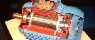
Stepper motor driver circuit
The stepper motor driver circuit does not contain expensive parts or programmable controllers. Operation can be adjusted over a wide range using potentiometer PR1. There is a change in the direction of rotation of the engine. The stepper motor coils are switched using four MOSFETs T1-T4. The use of high-power transistors of the BUZ10 type in the block will allow you to connect motors even with very high current.
Laboratory switching power supply. Part 3. LBP on 555 timers
Without a doubt, the brainchild of an electronics engineer allowed it to occupy its prominent niche in the history of technical inventions. In terms of sales, this device has surpassed any other since its introduction. In the second year of its existence, the 555 chip became the most purchased part.
View gallery
The leadership remained in all subsequent years. The 555 chip, whose use increased every year, sold very well. For example, in 2003, more than 1 billion copies were sold. The configuration of the unit itself has not changed during this time. It has existed for over 40 years.
The appearance of the device came as a surprise to the creator himself. Camenzind's goal was to make an information system that was flexible in use, but he did not expect that it would be so multifunctional. Initially, it was used as a timer or pulse generator. The 555 chip, whose use has increased at a rapid pace, is now used in everything from children's toys to spaceships.
The device is durable because it is based on bipolar technology, and nothing special is required to use it in space. Only test work is carried out with extreme rigor. Thus, when testing the NE 555 circuit, individual trial specifications are created for a number of applications. There are no differences in the production of circuits, but the approaches to output inspection differ markedly.
The appearance of the circuit in domestic electronics
The first mention of innovation in Soviet literature on radio engineering appeared in 1975. An article about the invention was published in the Electronics magazine. Microcircuit 555, an analogue of which was created by Soviet electronics engineers in the late 80s of the last century, was called KR1006VI1 in domestic radio electronics.
In production, this part was used in the assembly of Elektronika VM12 video recorders. But this was not the only analogue, as many manufacturers around the world created a similar device. All units have a conventional DIP8 package, as well as a small SOIC8 package.
Circuit Specifications
The 555 chip, a graphical representation of which is presented below, includes 20 transistors. On the block diagram of the device there are 3 resistors with a resistance of 5 kOhm. Hence the name of the device “555”.
The main technical characteristics of the product are:
- supply voltage 4.5-18V;
- maximum output current 200 mA;
- Energy consumption is up to 206 mA.
If we look at its output, it is a digital device. It can be in two positions - low (0V) and high (from 4.5 to 15 V). Depending on the power supply, the figure can reach 18 V.
Location of pins and designation on diagrams [edit | edit code ]
most often available in PDIP8 and SO8 packages, but other package options are also available. On diagrams it is usually indicated in the form of a rectangle with the inscription “G1/GN”, which stands for a specialized generator used to generate single pulses or series of pulses. The pin layout is standard for all chips of the same type:
| Pin No. NE555 | Pin No. NE556 | Designation | Alternative designation | Purpose | Description |
| 1 | 7 | GND | -U | General | Common wire, minus power |
| 2 | 6 / 8 | TRIG | S | Launch | When the voltage at this output falls below 1/3 of VCC, a high level voltage appears at the output, and the timing begins. |
| 3 | 5 / 9 | OUT | Q or without designation | Exit | This pin generates one of two voltages, approximately corresponding to GND and V CC - 1.5 V, depending on the state of the timer. |
| 4 | 4 / 10 | RESET | E | Reset (start enable) | When a voltage of less than 0.7 V is applied to this input, the output of the microcircuit is forced into a low-level state (switches to GND). This happens regardless of the state of other inputs, that is, this input has the highest priority. In other words, a high voltage level at this input (more than 0.7 V) allows the timer to start, otherwise the start is prohibited. |
| 5 | 3 / 11 | CTRL | UR | Control (divider control) | Connected directly to internal voltage divider. In the absence of an external signal, the voltage is 2/3 of V CC. Defines stop and start thresholds. |
| 6 | 2 / 12 | THR | R | Stop | When the voltage at this pin exceeds the voltage at the CTRL pin, the output goes low and the interval ends. A stop is possible if the TRIG input does not receive a start signal, since the TRIG input has priority over THR (exception is the KR1006VI1 microcircuit). |
| 7 | 1 / 13 | DIS | ◊ or ¤ Operating modes of NE555 [edit | edit code ] |
Device operating modes
The 555 chip has three operating modes:
- Monostable mode of the 555 chip. It works as a one-way single-ended. During operation, a pulse of a given length is emitted in response to the trigger input when a button is pressed. The output remains at low voltage until the trigger turns on. Hence it received the name waiting (monostable). This operating principle keeps the device inactive until turned on. The mode enables the inclusion of timers, switches, touch switches, frequency dividers, etc.
- Astable mode is a stand-alone feature of the device. It allows the circuit to remain in regenerative mode. The output voltage is variable: sometimes low, sometimes high. This scheme is applicable when it is necessary to give the device shocks of an intermittent nature (when the unit is turned on and off for a short time). The mode is used when turning on LED lamps, operates in a logical clock circuit, etc.
- Bistable mode, or Schmidt trigger. It is clear that it operates using a trigger system in the absence of a capacitor and has two stable states, high and low. The low trigger value becomes high. When the low voltage is released, the system rushes to a low state. This scheme is applicable in the field of railway construction.
555 timer pins
The 555 generator chip includes eight pins:
View gallery
- Pin 1 (ground). It is connected to the negative side of the power supply (common wire of the circuit).
- Pin 2 (trigger). It supplies high voltage for a period of time (it all depends on the power of the resistor and capacitor). This configuration is monostable. Pin 2 controls pin 6. If both are low, the output will be high. Otherwise, if the voltage is high on pin 6 and low on pin 2, the output on the timer will be low.
- Pin 3 (output). Outputs 3 and 7 are in phase. By applying a high voltage of approximately 2 V and a low voltage of 0.5 V, up to 200 mA will be obtained.
- Pin 4 (reset). The voltage supply to this output is low despite the 555 timer operating mode. To avoid accidental resets, this output should be connected to the positive side when in use.
- Conclusion 5 (control). It provides access to the comparator voltage. This pin is not used in Russian electronics, but by connecting it, you can achieve wide control possibilities for the 555 device.
- Pin 6 (stop). Included in comparator 1. It is opposite to pin 2 and is used to stop the device. This results in low voltage. This output can accept sine and square wave pulses.
- Pin 7 (bit). It is connected to the transistor collector T6, and the emitter of the latter is grounded. When the transistor is open, the capacitor discharges until it closes.
- Pin 8 (positive power side), which ranges from 4.5 to 18 V.
Circuit Features and Details
- four phase stepper motor control
- smooth adjustment of rotation speed within the entire range
- changing the direction of rotation of the motor
- possible engine stop
- 12V DC power supply
Parts – IC1: 4070, IC2: 4093, IC3: 4027, T1-T4: BUZ10, BUZ11
The stepper motor driver unit is assembled on the printed circuit board shown in the figure. We install, as a rule, starting with soldering resistors and sockets for integrated circuits, and finally electrolytic capacitors and high-power transistors.
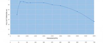
The unit, assembled from proven components, does not require configuration and starts immediately after power is applied. With the values of the elements indicated in the diagram, it allows a 5.25” engine to operate and changes the rotation speed in the range of 40 rpm. up to 5 rpm
Useful: Artificial load for the power supply
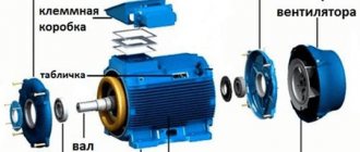
TechnoGen
A blog dedicated to radio electronics, microcontrollers and modern technologies.
24.04.2013
A simple PWM controller 0-100% for an LED lamp on a 555 timer, or upgrading a floor lamp
| PWM circuit 0-100% |
| All electronics |
| LEDs |
For testing, we placed it on a shallow radiator (the flux will definitely be washed off)).
| PWM |
Let's hope that the drivers are not unsoldered from the copper busbars)
:
Before soldering this circuit, I want to ask: does it really work, is it really 0%-100%?
It really works. True, there is one drawback when using powerful LEDs - even at 1% PWM, the LEDs begin to glow quite well (in an incident, this topic was even raised and a software PWM was written specifically for LEDs on a microcontroller). There is 0%, 100% - I don’t remember exactly, but maybe it’s 96%. Unfortunately there is no video of the work, but we are happy with the device.
I assembled your circuit, but the 555 began to get very hot. Having thought about it, I decided to install a 100 Ohm current-limiting resistor at the output. After which the circuit started working, but the brightness adjustment is the same as in the direct circuit. As I understand it, the diagram is the result of modeling, do you have a working diagram?
If the timer gets hot, it means you assembled something incorrectly. Is there a field worker at the exit? Double-check all ratings and diagram. This is not only a simulated circuit, but also one assembled in reality, the only thing is that I cannot take a video of the work, since I no longer have the device. As a last resort, use an oscilloscope to see what is happening at the output.
Help with cooler thermostat up to 1A
I can’t help with the regulator, since I didn’t assemble it. There are a whole bunch of schemes on the Internet - choose and try.
Please upload the file for Proteus, otherwise I’m modeling and something doesn’t work?
Added to the article with a small addition. I just don’t remember - at the minimum PWM, that impulse is not perceived by the field worker, or without a resistor on the 3rd leg it is not there at all.
there legs 3 and 7 are mixed up in the diagram
“I had to use the timer a little “in reverse” - the output of the timer is used to charge/discharge the capacitor, and the discharge output of the capacitor is used as an output.” So everything is correct there. If they are swapped, the minimum PWM will be about 5%, but we needed 0.
DooMmen, good afternoon! Very interesting article. I’m not very strong in this whole matter yet and the following question arose: I have a 5 meter LED strip connected (the most common, 3528, 4.8 W/meter) - if you use your circuit to adjust the brightness, you don’t need to change anything (well, except remove connector J1 - I have one whole tape)? Is 24 W load normal for it? Thank you in advance ))
There is no need to change anything in the scheme. The transistor in the diagram is designed for a sufficiently high current, so it will withstand it.
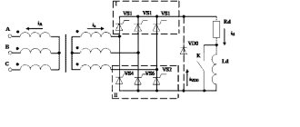
Bipolar Stepper Motor Controller
The circuit represents a low-cost and, above all, easy-to-assemble alternative to available microprocessor-based bipolar stepper motor controllers. Recommended where control accuracy plays a lesser role than price and reliability.
The circuit diagram can be divided into the following blocks:
- serial chip generating bit strings,
- local clock generator,
- coil power control circuit,
- H-bridge output buffers,
- protection circuits for input control signals.
The controller must be powered by a constant voltage, well filtered, preferably stabilized.
Now a few words about the H-bridges that will work with this driver. They must accept all possible logic states (00, 01, 10, 11) at their inputs without risk of any damage. It’s just that in some configurations of bridges built from discrete elements, simultaneous activation of two inputs is prohibited - they naturally cannot be used with this controller. Bridges made in the form of integrated circuits (for example L293, L298) are resistant to this.
And finally, the third version of the controller, based on STK672-440 microcircuits, has all the necessary protections and functions, see the link.
Operating modes, description of characteristics and pin assignments of the NE555 chip
When developing electronic devices, there is often a need to generate pulses of a given length or to generate a rectangular signal with a given frequency and a certain length-to-pause ratio. It will not be difficult for an experienced designer to design such a device using individual digital elements, but it is more convenient to use a specialized microcircuit for this purpose.
What is the NE555 chip and where can it be used?
The NE555 chip was developed in the 70s of the last century and is still very popular among professionals and amateurs. It is a timer housed in a housing with 8 pins. Available in DIP or various surface mount (SMD) versions.
The microcircuit contains two comparators - upper and lower. A reference voltage equal to 2/3 and 1/3 of the supply voltage is generated at their inputs. The divider is formed by resistors with a resistance of 5 kOhm. Comparators control the RS flip-flop. A buffer amplifier and a transistor switch are connected to its output. Each comparator has one free input; it serves to supply external control signals. The upper comparator is triggered when a high level appears and turns the output of the microcircuit to a low level. The lower one “watches” for a decrease in voltage below 1/3 VCC and sets a logical one at the timer output.
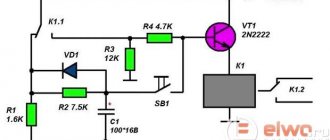
Example No. 1 - Darkness alarm.
The circuit beeps when darkness falls. While the photoresistor is illuminated, pin #4 is set low, which means the NE555 is in reset mode. But as soon as the lighting drops, the resistance of the photoresistor increases and a high level appears at pin No. 4 and, as a result, the timer starts, emitting a sound signal.
Electric soldering iron with temperature control
Power: 60/80 W, temperature: 200'C-450'C, quality…
Main characteristics of the NE555 chip
The characteristics of the timer from different manufacturers may differ within small limits, but no one has any fundamental deviations (except for microcircuits of unknown origin, you can expect anything from them):
- The supply voltage is usually indicated from +5 to +15 V, although datasheets contain limits of 4.5...18 V.
- The output current is 200 mA.
- Output voltage - maximum VCC minus 1.6 V, but not less than 2 V with a supply voltage of 5 V.
- Current consumption at 5 V is no more than 5 mA, at 15 V – up to 13 mA.
- The error in forming the pulse duration is no more than 2.25%.
- The maximum operating frequency is 500 kHz.