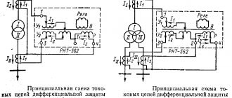
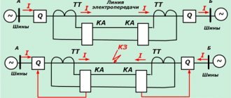
This article will discuss typical connection diagrams for current transformer (CT) windings and relays.
In three-phase AC electrical networks of all voltage classes, CTs for powering relay protection devices are installed in two or three phases: as a rule, in 6 and 10 kV networks with low ground fault currents in two phases (A and C), in 35 kV networks and necessarily in networks of 110 kV and above in three phases. All three phases are equipped with CTs in networks with voltages up to 1 kV, if they operate with a solidly grounded neutral.
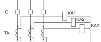
When performing current protection, the following four schemes for connecting the secondary windings of the CT and the current circuits of the current relay are used [L1, p. 41]:
- full star (three-phase, three-relay);
- partial star (two-phase, two-relay);
- partial star with a relay in the return wire (two-phase, three-relay);
- switching on a relay for the current difference between two phases (two-phase, single-relay).
Circuits are characterized by the ratio of the relay current lp to the secondary current I2 of the CT, called the circuit coefficient.
TT full star diagram
In the full star circuit (Fig. 1, a), secondary currents of the measuring transformers pass through the relay, therefore the circuit coefficient kcx = 1.
Protection can be triggered by any type of short circuit. This scheme is usually used in networks with a solidly grounded neutral, in which not only interphase, but also single-phase short circuits can occur, accompanied by the flow of current in one phase. In networks with an isolated (compensated) neutral (6-35 kV), the circuit, as a rule, is not used, since in these networks only phase-to-phase short circuits can occur, to fix which it is enough to have current transformers in two phases. The circuit is relatively expensive, as it requires three CTs and three current relays.
RELAY PROTECTION AND AUTOMATION OF ELECTRIC POWER SYSTEMS
Transcript
1 SECONDARY VOCATIONAL EDUCATION E. A. KIREEVA, S. A. TSYRUK RELAY PROTECTION AND AUTOMATION OF ELECTRIC POWER SYSTEMS TEXTBOOK Recommended by the Federal State Institution "Federal Institute for Educational Development" as a textbook for use in the educational process of educational institutions implementing secondary vocational education programs in the specialty “Power stations, networks and systems” Review registration number 47 dated March 12, 2010 FGU “FIRO” 3rd edition, stereotypical
2 UDC (075.32) BBK ya723 K43 Reviewers: Rector of the Institute for Advanced Training of Power Engineers, Dr. Tech. sciences, prof. O.A. Tereshko; deputy Head of the Department of Power Supply Systems for Missile Systems VA Strategic Missile Forces named after. Peter the Great, Ph.D. tech. Sciences V.V. Zorinets K43 Kireeva E.A. Relay protection and automation of electrical power systems: a textbook for students. institutions prof. education / E.A. Kireeva, S.A. Tsyruk. 3rd ed., erased. M.: Publishing House, p. ISBN Schemes, principles of operation, areas of application of current protection and calculations of their settings are considered. Basic information about distance and high-frequency protection, protection of transformers, motors, buses and lines is provided. The circuits and operating principles of automatic restart, automatic transfer switch, automatic frequency shedding and frequency automatic restart, as well as microprocessor-based protection devices are described. The textbook can be used when mastering the professional module PM.02 “Operation of electrical equipment of power plants, networks and systems” (MDK.02.02) in the specialty “Electrical stations, networks and systems”. For students of secondary vocational educational institutions. UDC (075.32) BBK ya723 The original layout of this publication is the property of the Publishing House, and its reproduction in any way without the consent of the copyright holder is prohibited ISBN E. A. Kireeva, S. A. Tsyruk, 2010 Educational Publishing House, 2010 Design. Publishing, 2010
3 PREFACE Relay protection is the most important and most critical component of automation used in modern energy systems. It automatically eliminates damage and abnormal conditions in the electrical part of power systems, ensuring their reliable operation. Currently, relay protection is becoming increasingly important due to the growth of power plant capacities and the increase in voltage of electrical networks. There is a gradual transition of relay protection and automation to a microprocessor base. Further improvement of relay protection and automation will follow the path of wider use of digital technology. Its advantage is the ability to record parameters that determine the operation of relay protection and automation in pre-emergency and emergency modes, with subsequent transmission of information to dispatch communication points. This textbook reflects classic and modern relay protection and automation devices that are successfully operated in Russian power systems. When writing this textbook, the authors used their many years of experience in teaching a similar discipline at the Moscow Energy Institute (Technical University), as well as their books and articles on relay protection, automation and telemechanics. The textbook covers the main issues and characteristic features of relay protection and automation of electrical power systems and industrial power supply systems. Considerable attention is paid to microprocessor relay protection and high-speed automation devices.
4 LIST OF ACCEPTED ABBREVIATIONS AVR AGP AD APV AChR BAVR BP BPN BPNS BPT VL VN HF GHF GPP DGR DO DTZ ZRU IMS IO ION IOT ISP KZ KRU LO MDS MOTS MTZ NN NTT OVD PA PHF PON PS PTT PUE RZ RP automatic in Switching on the reserve automatic extinguishing fields asynchronous motor automatic restart automatic frequency unloading high-speed ATS power supply voltage power supply voltage power supply stabilized current power supply overhead line high voltage high frequency HF generator main step-down substation arc suppression reactor remote element (measuring) differential current protection closed switchgear integrated circuit measuring voltage measuring element current measuring element stabilized power source short circuit complete switchgear logical element magnetomotive force maximum single-phase current protection maximum current protection low voltage saturable current transformer motor excitation winding emergency automatic receiver HF starting voltage element intermediate CT substation rules for electrical installations relay protection distribution point 4
5 RS SD SSH TAPV TN TNP TO TT TTF CHPP UO Level USZ CHAPV CHEAZ EMF ES resistance relay synchronous motor busbars three-phase automatic reclosure voltage transformer zero-sequence current transformer current cut-off current transformer three-transformer filter combined heat and power plant control element circuit breaker failure redundancy device fault signaling device frequency automatic reclosure Cheboksary Electrical Equipment Plant electromotive force electrical system
6 Chapter 1 DAMAGES AND ABNORMAL OPERATING MODES IN ELECTRIC POWER SYSTEMS 1.1. General Information Electric power systems can experience both damage and abnormal operating conditions. Damages are emergency modes; they can lead to the appearance of significant currents and a deep decrease in voltage on the buses of power plants and substations. Fault current can cause destruction at the fault location and dangerous heating of the wires. A decrease in voltage disrupts the normal operation of electricity consumers and the stability of parallel operation of power plants in the energy system [14]. Abnormal modes are not emergency conditions, since they usually only lead to a deviation of voltage, current and frequency from permissible values. When the frequency and voltage decrease, there is a danger of disruption to the normal operation of consumers and the stability of the power system, and an increase in voltage and current can lead to equipment damage. To reduce destruction at the site of damage and ensure normal operation of the undamaged part of the power system, it is necessary to quickly disconnect the damaged section. The dangerous consequences of abnormal modes can be avoided by timely taking appropriate measures to eliminate them (for example, reducing the current when it increases), and, if necessary, turning off electrical equipment if the created mode is unacceptable for it. Relay protection reacts to the occurrence of damage and abnormal conditions, which detects them and acts in the event of damage to turn off, and in the event of abnormal conditions, a signal or shutdown. Thus, relay protection is the main type of electrical automation, without which normal operation of power systems and electrical networks is impossible. 6
7 1.2. Types of damage The main type of damage to lines is short circuits (short circuits). The causes of short circuits can be violations of the insulation of electrical equipment due to wear or overvoltage, erroneous actions of operating personnel, overlapping of insulators when they are contaminated, violation of insulation by animals and birds, etc. Possible types of short circuits are given in Table. 1.1 With a three-phase short circuit, all three phases are closed to each other at one point. The three-phase short circuit point is designated K (3). Currents, voltages, powers related to a three-phase short circuit are designated I (3), U (3), S (3), respectively. Three-phase short circuit is the most severe type of damage, causing the largest short circuit currents. Therefore, a three-phase short circuit is calculated when determining the maximum short-circuit current. With a two-phase short circuit, two phases are shorted together. The point of a two-phase short circuit is designated K (2). Currents, voltages, Types of faults Table 1.1 Diagram Three-phase short circuit Type of fault Two-phase short circuit Two-phase short circuit to earth Double fault to earth Single-phase short circuit to earth Single-phase short circuit to earth 7
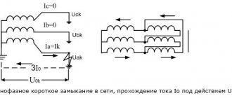
8 powers related to a two-phase short circuit are designated I (2), U (2), S (2), respectively. Two-phase short circuit currents contain only positive and negative sequence components. With a two-phase short circuit to ground, a short circuit between two phases is accompanied by a short circuit of the fault point to ground (in systems with grounded neutrals). The point of a two-phase ground fault is designated K (1,1). Currents, voltages, powers related to a two-phase ground fault are designated I (1,1), U (1,1), S (1,1), respectively. Two-phase ground fault currents contain direct, negative and zero sequence components. A two-phase ground fault is the most severe after a three-phase fault for the stability of the power system and electricity consumers. A double ground fault is a consequence of long-term operation of a network with a single-phase ground fault. A ground fault of another phase at another point in the network occurs due to increased (to phase-to-phase) voltage values of undamaged phases relative to ground. With a single-phase short circuit, one of the phases is shorted to ground or to the neutral wire. The single-phase short circuit point is designated K (1). Currents, voltages, powers related to a single-phase short circuit are designated I (1), U (1), S (1), respectively. Single-phase short circuit currents have direct, negative and zero sequence components. There are also other types of short circuits associated with wire breaks and simultaneous short circuits of wires of different phases. A three-phase short circuit is symmetrical, since all three phases are in the same conditions. All other types of short circuits are asymmetrical, since the phases do not remain under the same conditions, and the current and voltage systems are distorted. Three-phase short circuits occur relatively rarely (5% of the total number of short circuits). The most common faults are single-phase to ground. They account for up to 65% of the total number of short circuits. As is known, networks with voltages of 6, 10, 20 and 35 kV operate with an isolated neutral or with a neutral grounded through an arc suppression reactor (ARR), which has a high inductive reactance. Operation of a network with an isolated neutral is considered acceptable if the current at the point of a ground fault in networks with voltages of 6, 10, 20 and 35 kV does not exceed 30, 20, 15 and 10 A, respectively. At higher currents, the neutral is grounded through the DGR. The single-phase ground fault current is determined by the phase capacitances relative to the ground. Closed-phase voltage relative to ground due to low ground fault current 8
9 can be considered equal to zero at any point in the network. The ground fault current in a network with an isolated neutral contains components of the positive, negative and zero sequences. The probability of occurrence of one or another type of short circuit is different. In a network with a solidly grounded neutral (110 kV and above), a large short-circuit current passes at the fault point. In a network with an isolated or neutral grounded through an arc suppression reactor, the single-phase ground fault current has small values determined by the capacitance of the network wires relative to the ground. At the location of the short circuit, as a rule, an electric arc occurs, the resistance of which is usually neglected when calculating fault currents. If necessary, the arc resistance can be taken into account in accordance with the approximate expression [14] R d 1050 ld ª I, where l d arc length, m; I d arc current, A. d 1.3. Abnormal modes Abnormal modes include: equipment overload; voltage increase above the permissible value; swings that occur when the synchronous operation of power plant generators in the energy system is disrupted; asynchronous mode of a synchronous generator without excitation (for example, when the field suppression machine is turned off). The most common abnormal mode is an overload of electrical equipment caused by the flow of overcurrent, i.e., a current exceeding the rated one. Overload occurs during technological production processes, in post-emergency conditions, during expansion of production and increasing loads, during preventive and repair work. When overloaded, additional heating of electrical equipment occurs, which leads to accelerated aging of the insulation of live parts. To prevent damage to the equipment when it is overloaded, measures must be taken to unload it or (if necessary) turn it off. An increase in voltage that is dangerous for the insulation of equipment can occur, for example, when a long high-voltage line with high capacitance is switched off or switched on one side. Elimination of dangerous voltage increases in ultra-high voltage networks is carried out using special automation. 9
10 Swinging is a very dangerous abnormal mode that affects the operation of the entire power system. In terms of the nature of changes in current and swing voltage, they are similar to a short circuit. Most relay protection devices (RP) can disconnect protected lines during swings. However, these outages are chaotic in nature, which can lead to partial or complete disruption of power supply to consumers. In asynchronous mode, as a rule, a pulsation of the generator stator current occurs, which is unacceptable for some types of generators, especially during long-term operation in this mode. Test questions 1. What damage can occur in electrical power systems? 2. What abnormal conditions can occur in electrical power systems? 3. How do abnormal modes differ from emergency modes? 4. What are two-phase short circuits? 5. Which short circuits are symmetrical? 6. What are the consequences of overloading electrical equipment?
CT partial star circuit
In the partial star circuit (Fig. 1, b), secondary currents of CTs installed in phases A and C pass through the current relay. The circuit coefficient kcx = 1. The circuit is widely used in networks with an isolated neutral, since it ensures the disconnection of any phase-to-phase short circuit ( two-phase or three-phase).
The disadvantage of the circuit is the reduced (2 times compared to the previous circuit) sensitivity of the maximum current protection with a two-phase short circuit AV behind the transformer with the winding connection circuit U/D-11, since in this case the current passing through the protection relay is 2 times less than in full star diagram.
Protection principle
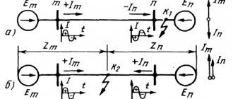
Distance protection (DP) is a name that indicates that it reacts to the distance to the short circuit point. To be more precise: the logic of its operation depends on the location of the closure point, which is determined by the protection.
She does this using devices called resistance relays.
Their task: to indirectly measure the resistance from the location of the protection to the point of short circuit. And for this, according to Ohm’s law, it requires not only current, but also voltage received from a voltage transformer installed on the substation buses.
The resistance relay is activated under the following conditions:
Here Zset is the relay response resistance setting. The measured quantity is fictitious, since in some operating modes (for example, during swings) its physical meaning as resistance is lost.
The operating settings, and, consequently, the resistance relays of the DZ, as a rule, are at least three.
The protected area is divided into sections called zones. The response time for each zone is different. And the resistance relay setting is equal to the resistance up to the point at the end of the corresponding zone. To clarify, let us recall the example of substations and lines.
Setting of the first DZ zone
It is calculated so that it protects only its outgoing line. But not to the very end, but taking into account the error in measuring resistance - 0.7-0.85 of its length. When the first remote sensing zone is triggered, the line is switched off with the minimum possible time delay, since it is guaranteed to be located there.
Second zone remote sensing
Reserves protection failure of the next substation. Why does she react to the end of line No. 2. And the first fault zone for the second line switch from substation No. 2 is set to resistance to the same short circuit point, but from the busbars of this substation. But the time delay of 2 remote control zones of substation No. 1 is longer than 1 remote sensing zone of substation No. 2.
This ensures the required selectivity: the second line circuit breaker from substation No. 2 will turn off before the protection time relay at substation No. 1 operates.
Third zone remote sensing
Necessary to reserve protection for the next line, if available. No additional number of zones is provided.
Watch an interesting video about setting up distance protection below:
Scheme of a partial star CT with a relay in the return wire
In a partial star circuit with a relay in the return wire (Fig. 1, c), the sum of the secondary currents of phases A and C or (in case of phase-to-phase short circuits) the current of phase B with the opposite sign passes through the 3KA relay connected to the return wire [L1, p. 42]:
The circuit has the advantage of a partial star circuit (using two CTs) and has the same sensitivity for two-phase short circuits behind the U/D-11 transformer as a full star circuit. Circuit coefficient kcx = 1.
The partial star circuit with or without a relay in the return wire has found widespread use in current protection of lines with voltages up to 35 kV inclusive (i.e. in networks with an isolated neutral).
Relay protection circuit coefficient
Relay protection
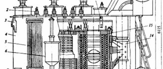
Recently, the number of cases of failure of power transformers due to the natural aging of winding insulation and unauthorized draining of oil from the transformer tank has increased, resulting in irreversible processes in the winding insulation. Periodic maintenance and repair, diagnostics, and testing of transformers for their suitability for further operation do not exclude the possibility of damage, our Ukrainian authors believe. To minimize damage, they offer their own method of constructing transformer relay protection.
| Alfred Manilov, engineer, PTI "Kievorgbud" | Anna Novichkova, engineer, High-Voltage Union - Ukraine LLC |
| Kyiv, Ukraine | |
Relay protection and automation design
The relay protection device is a circuit consisting of the following parts:
- Starting elements – voltage, current, power relays. Designed to monitor the operating mode of electrical equipment, as well as detect violations in the circuit.
- Measuring elements - can also be located in starting elements (current and voltage relays). The main purpose is to launch other devices, send a signal as a result of detecting an abnormal operating mode, as well as instantly turn off devices or with a time delay.
- Logical part. It is represented by timers, as well as intermediate and indicating relays.
- Executive part. Responsible directly for turning off or turning on switching devices.
- Transmitting part. Can be used in phase differential protection.
Finally, we recommend that you watch a useful video on the topic:
That's all we wanted to tell you about the purpose of relay protection and the requirements for it. We hope you now know what relay protection and automation is, what its scope is and what it consists of.
It will be useful to read:
