A computer power cable is a special cord, the connector of which is inserted into a special socket of the power supply unit (PSU) of the computer, and the plug located at the other end is inserted into a regular household outlet with a voltage of 220V. Despite the apparent simplicity of this cord and the small number of varieties, its correct selection and connection have a significant impact on the performance and duration of operation of the computer and the devices included in its system unit: motherboard, video card, hard drive, RAM sticks.
Standard power cord for personal computers
Power cables for the system unit
The system unit and the devices inside it are powered from the 220 network using the following wires:
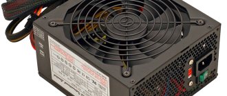
- Power cord - a cable with a Euro plug and a 2 or 3 socket connector used to supply alternating current from a household network to the power supply of a PC or monitor. Such cords are also used to power peripheral devices such as printers, scanners, and MFPs.
- The power supply cable for IDE type devices (Molex) is a cable consisting of four wires not connected to each other with a four-pin connector at the end. It is used to connect devices such as a hard drive or optical drive to the power supply. Also, often along with such a cable there is a three-pin adapter connected to it for powering the processor cooler. This power cable is used to connect hard drives and CD-ROMs of older models. Among the wires of modern power supplies, it is rare.
- A cable for SATA type devices is a cable consisting of 5 cores with a 15-pin connector at the end. Used to power new models of hard drives and hard drives.
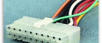
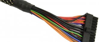
- Powering the motherboard is the largest cable consisting of a large number of unconnected wires with a 20 or 24 pin connector at the end. Connect it to a special socket. To protect against incorrect connection, there is a special latch on the connector and cutouts on the pins. Thanks to this, the connector is inserted in only one correct position.
Motherboard power cable
- The power cable for the processor is a 4- or 8-pin small cable that is connected directly to the processor through a separate special socket.
A more detailed description of connecting a particular power cable can be found in numerous videos on the Internet and in the instructions included with each system unit device.
Marking for power supply wires
To prevent maintenance and repair of motherboards and power supplies from being a terrible pain, a uniform color coding standard is used. Each wire is assigned a color that is tied to the voltage applied to that wire. Letter marking is used only in technical documentation, where it is possible to compare a color with its letter value. For convenience, all pinout information for each connector is presented in tables.
Connector mat. boards
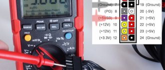
The ATX form factor has been the dominant standard for all desktop PCs since 2001. Based on this form factor, below I will give a table of the pinout of the contact (bus) of the PC power supply that connects to the motherboard.
| Motherboard connector | ||||
| No. Pin | Meaning | Color | No. Pin | Meaning |
| 1 | 3.3V | Orange | 13 | 3.3 V/ +3.3 V sense |
| 2 | 3.3V | Orange | 14 | -12 V |
| 3 | GND | Black | 15 | GND |
| 4 | +5 V | Red | 16 | Power ON/PC ON |
| 5 | GND | Black | 17 | GND |
| 6 | +5 V | Red | 18 | GND |
| 7 | GND | Black | 19 | GND |
| 8 | Power Good | Grey | 20 | -5 V |
| 9 | 5VSB (standby mode +5 V) | Violet | 21 | +5 V |
| 10 | +12 V | Yellow | 22 | +5 V |
| 11 | +12 V | Yellow | 23 | +5 V |
| 12 | 3.3V | Orange | 24 | GND |
GND - ground;
Contacts 8, 13, 16 - control signals;
Pin 13 has 2 wires at once, one of them is a tap. These two wires are of smaller gauge.
The table is universal and suitable for all ATX form factor motherboards.
Advice!
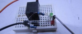
By shorting pins 15 and 16 or 16 and any black GND, you can start the power supply without connecting the motherboard.
Molex connectors
Outdated, but not lost to history, the 4 Pin PATA connector is a universal product. If the required connector is missing, then a molex + 4 Pin to 6 Pin adapter will allow you to record the video card. A molex + 4 Pin - 3 Pin adapter will allow you to connect another cooler in the system unit.
Why is it universal? Because the “demanded” voltage is used at the contacts.
The pinout of the molex connector is as follows.
| HDD IDE (ATA) hard drive power connector - Molex | ||
| No. Pin | Color | Meaning |
| 1 | Yellow | +12 V |
| 2 | Black | GND |
| 3 | Black | GND |
| 4 | Red | +5 V |
Also, using a molex connector, several devices, components, splitters, adapters can be connected to the power supply, but limited in quantity by the power of the power supply and the cooling system in the PC case. With the help of splitters, you can get from one to two or three molex connectors.
SATA connectors
SATA connections are primarily used in hard drives and optical drives for power and information transfer. Power is supplied to the 15 Pin connector pins using five wires. This is where the rumor came from that SATA is 5 Pin, although this is a wrong statement.
The pinout is presented in the table.
| SATA | ||
| No. Pin | Color | Meaning |
| 1 | Orange | +3.3 V |
| 2 | Orange | +3.3 V |
| 3 | Orange | +3.3 V |
| 4 | Black | GND |
| 5 | Black | GND |
| 6 | Black | GND |
| 7 | Red | +5 V |
| 8 | Red | +5 V |
| 9 | Red | +5 V |
| 10 | Black | GND |
| 11 | Black gray | GND - Signal |
| 12 | Black | GND |
| 13 | Yellow | +12 V |
| 14 | Yellow | +12 V |
| 15 | Yellow | +12 V |
The pinout indicated in the table refers to pre-installed SATA power connectors, because it has a gray signal wire and an orange one with a voltage of 3.3 V. This type of wire is necessary for the correct operation of RAID arrays (combining several physical disks into one logical element) and replacement hard drives “on hot” (with the machine turned on, to turn on - first the interface, then the power, to turn off - first the power, then the interface).
By the way, modern hard drives powered by a SATA connector can also be powered by 4 Pin PATA. Hard drives have voltage converters, so you can power the HDD without any problems using a PATA (molex in mind) - SATA adapter if there are no SATAs or the power supply has run out.
Graphics card connectors
Modern power supplies have 6 and 8 Pin connectors for connecting graphic cards. As mentioned earlier, 2 more contacts are needed for additional power supply to a powerful video card.
The video card receives power from the PCI-E bus, with a power of up to 75 Watts. If you have a gaming video card, ala GeForce GTX 1050 Ti, then it needs additional power (in this case, one 6 Pin connector is allocated).
6-pin connectors add 75 watts of power to video cards.
8 pins - 150 watts.
Graphic monsters in the gaming industry, design, rendering and mining can use 6 and 8 pin connectors at once, which will give a total of 300 Watts of power for one video card.
Here's a fact for you!
The GeForce GTX 1080 Ti video card uses two additional 8+8 Pin power connectors. You can calculate how much power is allocated for it yourself.
| 6 Pin PCI-E connector | ||
| No. Pin | Color | Meaning |
| 1 | Yellow | +12 V |
| 2 | Yellow | +12 V |
| 3 | Yellow | +12 V |
| 4 | Black | GND |
| 5 | Black | GND |
| 6 | Black | GND |
| 8 Pin PCI-E connector | ||
| No. Pin | Color | Meaning |
| 1 | Yellow | +12 V |
| 2 | Yellow | +12 V |
| 3 | Yellow | +12 V |
| 4 | Black | GND |
| 5 | Black | GND |
| 6 | Black | GND |
| 7 | Black | GND |
| 8 | Black | GND |
Such video cards require more powerful power supplies. You also need to take into account that when connecting several graphics cards on the same graphics chip via SLI (NVIDIA technology) or CrossFire (AMD technology), heat transfer increases, which must be regulated by additional cooling in the case. Additional power supply capacity will be required for cooling.
In some power supply models (may be indicated in the instructions or written on the packaging), the +12V supply lines may be separate.
Eight-pin connectors are also used to connect additional power to the central processor. However, 8 Pin for the video card and 8 Pin for the processor differ from each other in form factor and pinout, although they seem to be similar to each other.
Important!
If power for the graphics card is not supplied through the additional six or eight Pin connector (it is not connected or has stopped working), the video card may refuse to start on the computer or the PC itself may not start.
CPU connectors
For additional power supply to the central processing unit (CPU), there are 4 Pin and 8 Pin connectors. Which one to use depends on the power of the CPU (and on the connector, respectively). 4 Pin for the middle class, 8 for demanding ones.
These connectors may be present in power supplies:
- two at once;
- one of them;
- one collapsible eight-pin, consisting of two four-pin.
Increased power is mainly required for multi-core CPUs and for overclocking.
| CPU Connector 4 Pin | ||
| No. Pin | Color | Meaning |
| 1 | Black | GND |
| 2 | Black | GND |
| 3 | Yellow | +12 V |
| 4 | Yellow | +12 V |
| CPU Connector 8 Pin | ||
| No. Pin | Color | Meaning |
| 1 | Black | GND |
| 2 | Black | GND |
| 3 | Black | GND |
| 4 | Black | GND |
| 5 | Yellow | +12 V |
| 6 | Yellow | +12 V |
| 7 | Yellow | +12 V |
| 8 | Yellow | +12 V |
Other connectors
Other connectors mainly include the old 4 Pin floppy and 3-4 pin connectors for coolers.
The floppy connector is generally not included in the configuration of a modern power supply, but we will provide a table of its pinout. Just in case.
| FLOPPY 4 Pin | ||
| No. Pin | Color | Meaning |
| 1 | Red | +5 V |
| 2 | Black | GND |
| 3 | Black | GND |
| 4 | Yellow | +12 V |
3-4 Pin connectors are an undying classic. Cooling in powerful stationary PCs was, is, and will be. There can be quite a lot of space for a cooler in a PC case, so you can’t do without adapters.
Also, the motherboard must have at least one cooler power connector (CPU FAN), which usually powers the CPU cooler. In modern motherboards, there are usually about 4 such connectors.
Let's go through the pinout of cooler connectors in the power supply. There are 2 options for 4 Pin and one for 3 Pin.
| Cooler, option 1 - 4 Pin | ||
| No. Pin | Color | Meaning |
| 1 | Black | GND |
| 2 | Yellow | +12 V |
| 3 | Green | Tachometer signal |
| 4 | Blue | PWM (PWM) |
| Cooler, option 2 - 4 Pin | ||
| 1 | Black | GND |
| 2 | Red | +12 V |
| 3 | Yellow | Tachometer signal |
| 4 | Blue | PWM (PWM) |
| Cooler connector 3 Pin | ||
| 1 | Black | GND |
| 2 | Red | +12 V |
| 3 | Yellow | Tachometer signal |
There is also an old two-pin option (ground - power), but now this option has practically become obsolete.
Let's go through those indicated in the table. The 3 Pin connector supplies power and rotates at maximum speed, the yellow wire acts as a tachometer and displays information about the number of revolutions per minute.
The 4 Pin connector has the same properties as the 3 Pin plus 4 PWM wire, which allows you to programmatically control the number of revolutions of the connected cooler.
If you have a 4 Pin cooler, but a 3 Pin connector, you can safely connect. The cooler will work, you just won’t be able to control the number of revolutions.
Characteristics
Antenna power supply
The main PC power cable, consisting of a 2 or 3 socket contact and a Euro plug, has the following characteristics:
- Type of cable used - three-core cables with a cross-sectional area of each core of 0.75-1.0 mm2 are used in power cords;
- Maximum supplied voltage - modern cords operate at voltages up to 240 V;
- Current strength - modern cords are designed for current strength up to 10 A;
- Current frequency – power cords operate at a current frequency of no more than 50 Hz.
Working in conditions where the maximum permissible values of these characteristics are exceeded is fraught with failure of not only the power cord itself, but also the entire PC.
What to do if you run out of USB ports
The USB interface is universal and supports up to 127 devices per controller. Consequently, more devices can be connected to the system unit, but how? Everything is very simple, for this they use a special USB hub , which has several USB ports, but uses only one USB port on the motherboard.
The main thing to consider when buying a USB hub is that it must be active , that is, have a separate power supply . Only in this case, you will be able to work with your peripherals in peace - the devices will not periodically “fall off” due to lack of power.
Choosing a wire to connect the computer to the electrical network
The correct choice of power cable for connecting a personal computer to the network is very important for the following reasons:
- Choosing a wire that is too short or, conversely, too long will create inconvenience when connecting your PC to the network - the cable will not reach the outlet or will get very tangled.
- A high-quality wire will withstand the maximum values of current strength, frequency, and voltage declared by its manufacturer. Cheap Chinese models often have greatly inflated values of the main characteristics, which negatively affects the performance of the PC.
- The selected high-quality wire will ensure the safety of not only the computer, but also the user working with it - reliable external insulation and the presence of grounding will maximally protect the person working on the PC from electric shock.
Monitor power cable from computer
Personal computer monitor power cable
The power cable for a personal desktop computer monitor is a cord consisting of two connectors: 3 pin and 3 female. The first one is connected to the monitor, the second one is connected to the power supply.
Thanks to this monitor power cord, there is no need to use an additional power cord.
The monitor is connected to the computer's video card using a special cable with two connectors such as VGA, DVI or HDMI.
Molex connectors
This type of 4 pin PATA connectors (Molex 8981) is the most common and universal. If the required connector is missing, using a Molex 8981 connector and a special adapter (for example, 4 pin —> 6 pin) you can supply power to the video card, or using another adapter (for example, 4 pin —> 3 pin) you can connect an additional fan.
The versatility of the connector is explained by the presence of the most “demanded” voltages on the contacts, the pinout of which looks like this:
- Yellow – +12V;
- Black – GND;
- Black – GND;
- Red – +5V.
Using the Molex 8981 connector, several different devices, adapters, adapters and splitters can be connected to the power supply, the number of which is limited by the power of the power supply and the cooling system inside the case. The splitters allow you to get two or three (tee) connectors from one Molex 8981 connector at once. Adapters are designed to replace the missing connector on the power supply by connecting to the Molex 8981 connector.
It will be interesting➡ Ways to check transistors for functionality
SATA connectors
Most modern storage devices, including hard drives and optical drives, use the SATA interface for both power supply and information transfer. Power via SATA is supplied through a 15-pin connector, to which 5 wires are connected, which is why the connector is called a 5-pin connector. But this definition is incorrect.
The connector pinout looks like this:
- Orange – +3.3V;
- Orange – +3.3V;
- Orange – +3.3V;
- Black – GND;
- Black – GND;
- Black – GND;
- Red – +5V;
- Red – +5V;
- Red – +5V;
- Black – GND;
- Gray – signal;
- Black – GND;
- Yellow – +12V;
- Yellow – +12V;
- Yellow – +12V;
This pinout is correct for the supplied SATA power connectors, since there is a gray signal wire and an orange one with a voltage of + 3.3V. The presence of these wires is required for correct operation in RAID arrays and for hot-swapping hard drives.
Different types of connectors.
Modern storage media powered by a SATA connector can also operate on four wires, like 4 pin PATA connectors. The devices have built-in voltage converters that help you use a PATA (Molex 8981) -> SATA power adapter to work with the drive, in the absence of a pre-installed SATA connector.
Computer power supply pinout
Connectors for video cards
Standard and higher-level power supplies use 6 and 8 pin connectors, or both may be present at once, for additional power supply to video cards. Modern video cards are designed to be installed in the PCI-E slot of the motherboard. Budget and entry-level video cards do not require additional power, but receive it from the PCI-E bus up to a maximum power consumption of 75 watts.
Gaming and professional video cards, possibly several cards connected using CrossFireX or SLI technology, depending on the “filling”, require increased power and power supply.
If the video card has average power consumption requirements, then an additional 6 or 8 pin connector is installed on it. The 6-pin connector adds 75 watts of power, and the 8-pin connector adds 150 watts. On very powerful video cards, two connectors can be used at once, and the total power consumed will be 300 watts. The pinout for these connectors looks like this:
- 8 pins: 1-2-3 – yellow +12V, 4-5-6-7-8 4 – black GND.
- 6 pins: 1-2-3 – yellow 12V, 4-5-6 – black GND.
Such components require increased power from the power supply, and it should also be taken into account that when operating in CrossFireX or SLI modes, increased heat dissipation will occur, and accordingly additional cooling power will be required. Depending on the model of the power supply, the lines for supplying +12V voltage may be separate, as written on the power supply casing or in its technical data sheet. 8 pin connectors are intended not only for powering video cards, but also for additional power supply to the processor.
Video card connectors.
It is worth noting that the connectors themselves are very similar in appearance and at first glance seem the same. In fact, the connectors have different pinouts and form factors; you should not try to insert the processor power connector into the video card connector or vice versa. If the video card requires additional power, but for some reason it is not connected or not supplied, then the card itself and the computer as a whole may fail to start.
Pinout
PSUs, regardless of power, are equipped with connectors for connecting to the chipset, HDD/SSD disk devices, video adapter, Molex, etc. I propose to consider each connection type separately so as not to get confused.
Motherboard
The main connector used here is 20-pin, the color designation of wires of which is generally accepted throughout the world. And if you look at the documentation for the chipset, you can find a letter designation there that makes it easier to understand the situation. Please note that the abbreviation GND (Ground) is “ground”, grounding. And the eighth, thirteenth and sixteenth pins are responsible for sending control signals. If you close contacts No. 16 and No. 15, the power supply will start even without connecting to the computer.
Motherboard connectors.
Computer Power Supply - Molex Wiring Diagram
It is a 4-pin connector, which is used to provide power to the graphics adapter, coolers and other devices. Two of the four wires supply 12/5 Volt DC power, and the pinout diagram looks like this:
It will be interesting➡ Connecting a fiber optic cable at home
Power for drives
Modern hard and solid-state drives, as well as optical drives, are connected to the power supply via a 15-pin connector, to which five wires of different colors are connected. In some devices, a different SATA connection scheme is possible - “4+1”, where instead of five wires there are four + one separate one for power.
Interesting on the topic: How to check a zener diode.
Color pinout for video cards
Budget video adapter models can be powered by the chipset, but if you have powerful equipment with additional cooling and a large amount of memory, you will need to connect wires directly from the power supply. Nowadays both 8-pin and 6-pin connectors are actively used:
CPU power
If your computer is highly equipped, then its needs correspond. In some cases, it is necessary to provide additional make-up for the process handler and the cooling system.
PC processor connection.
The most commonly used connectors are:
- 8-pin – all black wires are GND, and all yellow wires are 12 Volts;
- 4-pin – similar to the previous scheme.
But for coolers, so-called 3- or 4-pin FAN connectors are used:
- 4-pin: black – “ground”, green – signal for the tachometer, yellow – current 12 Volts, blue – PWM (PWM) – ability to control the rotation speed of the cooling fan;
- 4-pin: an alternative pinout is distinguished by the presence of a red wire - 12 Volts, and instead of green, a yellow wire is used - tachometer;
- 3-pin: GND grounding – black, power – red wire, yellow cable – tachometer. There is no cooler control.
So we figured out the issue of “pinout of wires in a computer power supply.” If you have questions about more modern models, leave messages under the article in the comment section.
How a modern computer power supply works - the pinout of wires is of interest to many users who want to understand the principle of operation of one of the most important hardware components of a desktop PC. Modular power supplies are becoming increasingly popular, where it is possible to disconnect unused elements, which will allow you to remove unnecessary cables. But in this publication I will talk about the wiring diagram of a conventional power supply installed in the vast majority of computers.
PC processor connection.
Pinout
PSUs, regardless of power, are equipped with connectors for connecting to the chipset, HDD/SSD disk devices, video adapter, Molex, etc. I propose to consider each connection type separately so as not to get confused.
Motherboard
The main connector used here is 20-pin, the color designation of wires of which is generally accepted throughout the world. And if you look at the documentation for the chipset, you can find a letter designation there that makes it easier to understand the situation.
Please note that the abbreviation GND (Ground) is “ground”, grounding. And the eighth, thirteenth and sixteenth pins are responsible for sending control signals. If you close contacts No. 16 and No. 15, the power supply will start even without connecting to the computer.
How to connect wires to the front panel
The front panel of the PC contains the following elements:
- Audio connectors: microphone + headphones;
- 2 USB 2.0 or 3.0 ports;
- Computer power button;
- Reset button;
- LED indicator for connecting the device to the network;
- LED indicator of hard drive operation;
- A speaker that emits a signal when a system error occurs (“beeper”).
From each of these elements comes a cable with corresponding connectors, which are connected to the sockets on the system (motherboard) board according to the instructions supplied with each specific motherboard model.
Thus, knowing what the power wire is, how to choose and connect it correctly, you can protect your PC from serious damage.
Connecting input/output devices to the system unit
Computer peripherals are universal and use a USB interface for connection.
Before connecting a scanner, printer, MFP and other input/output devices to the system unit, read the instructions for their correct installation. For example, some printers, when installing drivers, indicate step by step when you need to connect the device to the system unit and when to the power supply.
Video
The process of connecting the front panel elements is clearly shown in more detail in the following video.
Coffee capsules Nescafe Dolce Gusto Cappuccino, 8 servings (16 capsules)
435 ₽ More details
Coffee capsule Nescafe Dolce Gusto Cafe O Le Coffee with milk, 3 packs of 16 capsules each
1305 ₽ More details
Apple Chargers