The author of the article is a professional tutor, author of textbooks for preparing for the Unified State Exam Igor Vyacheslavovich Yakovlev
Topics of the Unified State Examination codifier: self-induction, inductance, magnetic field energy.
Self-induction is a special case of electromagnetic induction. It turns out that the electric current in the circuit, changing over time, influences itself in a certain way.
Situation 1
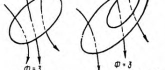
.Suppose that the current in the circuit increases. Let the current flow counterclockwise; then the magnetic field of this current is directed upward and increases (Fig. 1).
Rice. 1. The vortex field prevents the current from increasing
Thus, our circuit finds itself in the alternating magnetic field of its own current. The magnetic field in this case increases (together with the current) and therefore generates a vortex electric field, the lines of which are directed clockwise in accordance with Lenz’s rule.
As we see, the vortex electric field is directed against the current, preventing its increase; it seems to “slow down” the current. Therefore, when any circuit is closed, the current is not established instantly; it takes some time to overcome the braking effect of the resulting vortex electric field.
Situation 2
. Let us now assume that the current in the circuit decreases. The magnetic field of the current also decreases and generates a vortex electric field directed counterclockwise (Fig. 2).
Rice. 2. The vortex field maintains a decreasing current
Now the vortex electric field is directed in the same direction as the current; it maintains the current, preventing it from decreasing.
As we know, the work of an eddy electric field to move a unit positive charge around a circuit is the induced emf. Therefore we can give this definition.
The phenomenon of self-induction is that when the current in a circuit changes, an induced emf occurs in the same circuit
.
As the current strength increases (in situation 1), the vortex electric field does negative work, braking free charges. Therefore, the induced emf in this case is negative.
When the current strength decreases (in situation 2), the vortex electric field does positive work, “pushing” free charges and preventing the current from decreasing. The induced emf in this case is also positive (it is easy to verify that the sign of the induced emf, determined in this way, is consistent with the rule for choosing the sign for the induced emf, formulated in the sheet “Electromagnetic induction”).
Inductance
We know that the magnetic flux passing through the circuit is proportional to the magnetic field induction: . In addition, experience shows that the magnitude of the magnetic field induction of a circuit with current is proportional to the strength of the current: Therefore, the magnetic flux through the surface of the circuit, created by the magnetic field of the current in this very circuit, is proportional to the strength of the current: The proportionality coefficient is designated and called the inductance of the circuit:
(1)
Inductance depends on the geometric properties of the circuit (shape and size), as well as on the magnetic properties of the medium in which the circuit is placed (Do you catch the analogy? The capacitance of a capacitor depends on its geometric characteristics, as well as on the dielectric constant of the medium between the plates of the capacitor). The unit of inductance is henry (H).
Let us assume that the shape of the circuit, its dimensions and the magnetic properties of the medium remain constant (for example, our circuit is a coil into which a core is not inserted); The change in magnetic flux through the circuit is caused only by the change in current. Then, and Faraday’s law takes the form:
(2)
Thanks to the minus sign in (2), the induced emf turns out to be negative when the current increases and positive when the current decreases, which we saw above.
Let's consider two experiments demonstrating the phenomenon of self-induction when closing and opening a circuit.
Rice. 3. Self-induction when closing the circuit
In the first experiment, two light bulbs are connected in parallel to a battery, and the second one is connected in series with a coil of sufficiently high inductance (Fig. 3).
The key is initially open.
When the key is closed, light 1 lights up immediately, and light 2 lights up gradually. The fact is that an induced emf appears in the coil, which prevents the current from increasing. Therefore, the maximum current value in the second light bulb is established only after some noticeable time after the first light bulb flashes.
This delay time is greater, the greater the inductance of the coil. The explanation is simple: after all, then the intensity of the vortex electric field arising in the coil will be greater, and therefore the battery will have to do a lot of work to overcome the vortex field that decelerates the charged particles.
In the second experiment, a coil and a light bulb are connected in parallel to the battery (Fig. 4). The resistance of the coil is much less than the resistance of the light bulb.
Rice. 4. Self-induction when the circuit opens
The key is initially closed. The light bulb does not light up - the voltage on it is close to zero due to the low resistance of the coil. Almost all the current flowing in an unbranched circuit passes through the coil.
When the key is opened, the light flashes brightly! Why? The current through the coil begins to decrease sharply, and a significant induced emf arises, supporting the decreasing current (after all, the induced emf, as can be seen from (2), is proportional to the rate of change of the current).
In other words, when the key is opened, a very large vortex electric field appears in the coil, accelerating free charges. Under the influence of this vortex field, a current pulse runs through the light bulb, and we see a bright flash. If the inductance of the coil is sufficiently large, the induced emf can become significantly greater than the emf of the battery, and the light bulb will completely burn out.
You may not mind the light bulb, but in industry and energy this effect is a serious problem. Since when the circuit is opened, the current begins to decrease very quickly, the induced emf arising in the circuit can significantly exceed the rated voltage and reach dangerously large values. Therefore, in units that consume high current, special hardware precautions are provided (for example, oil switches in power plants) to prevent instantaneous opening of the circuit.
Electromechanical analogy
It is not difficult to notice a certain analogy between inductance in electrodynamics and mass in mechanics.
1. It takes some time to accelerate a body to a given speed; it is not possible to instantly change the speed of a body. With a constant force applied to the body, this time is longer, the greater the body mass.
It takes some time for the current in the coil to reach its maximum value; the current is not established instantly. The greater the inductance of the coil, the greater the current establishment time.
2. If a body hits a stationary wall, then the speed of the body decreases very quickly. The wall takes the blow, and its destructive effect is stronger, the greater the body mass.
When the circuit with the coil is opened, the current decreases very quickly. The circuit takes a “blow” in the form of a vortex electric field generated by the decreasing magnetic field of the current, and this “blow” is stronger, the greater the inductance of the coil. The induced emf can reach such large values that a breakdown of the air gap will damage the equipment.
In fact, these electromechanical analogies
extend quite far; they concern not only inductance and mass, but also other quantities, and turn out to be very useful in practice. We will talk about this more in the leaflet about electromagnetic vibrations.
What is self-induction - for dummies
Any electronic conductor has an alternating magnetic field, which generates an additional, so-called induction current. And if we consider an electrical circuit as a conductor, then when the current strength changes in it, the magnetic field will also change, which will provoke the appearance of a vortex electric field.
Such phenomena will cause the appearance of electromotive force (EMF) in the same circuit, which is self-induction. Thus, self-induction is considered a phenomenon during which an EMF occurs in an electrical conductor due to a change in current in the conductor itself. It is self-induction that prevents the current from acquiring a certain value when the electrical circuit is suddenly closed or opened, since the EMF in the conductor during the current increase is directed in the opposite direction relative to the power source and vice versa during its decrease.
The phenomenon of self-induction can be clearly seen when turning on or off 2 identical lamps that are connected in parallel.
In this case, the self-induction emf can be calculated using the formula:
Ɛ=-dФ/dt, where:
- Ɛ – direct EMF;
- dФ – changes in the magnetic field;
- dt – the period of time during which the changes occurred.
EMF is measured in volts when the unit of magnetic field is weber.
Self-induction
Let's imagine any electrical circuit whose parameters can be changed. If we change the current strength in this circuit - for example, we turn up the rheostat or connect another current source - the magnetic field will change. As a result of this change, an additional induced current will arise in the circuit due to electromagnetic induction, which we discussed above. This phenomenon is called self-induction, and the resulting current is called self-induction current.
| Magnetic flux formula for self-induction F = LI Ф - own magnetic flux [Wb] L - circuit inductance [H] I - current strength in the circuit [A] |
Online preparation for the OGE in physics will help you relieve stress before the exam and get a high score.
Self-induction is the occurrence of an EMF in a conducting circuit, created as a result of a change in current strength in the circuit itself.
Self-induction is somewhat reminiscent of inertia: just as in mechanics it is impossible to instantly stop a moving body, so the current cannot instantly acquire a certain value due to self-induction.
Let's imagine a circuit consisting of two identical lamps connected in parallel to a current source. If we connect a coil in series with the second lamp in this circuit, then when the circuit is closed, the following will happen:
- the first lamp will light up almost immediately,
- the second lamp will light up with a noticeable delay.
When the circuit is opened, the current strength quickly decreases, and the resulting self-induction emf prevents the decrease in magnetic flux. In this case, the induced current is directed in the same way as the original one. The self-induced emf can be many times greater than the external emf. This is why light bulbs burn out so often when the lights go out.
| Self-induced emf ξis — self-induction emf [V] ΔФ/Δt — rate of change of magnetic flux [Wb/s] ΔI/Δt - rate of change of current in the circuit [A/s] L - inductance [H] |
The minus sign in the formula for the law of electromagnetic induction indicates that the induced emf prevents the change in magnetic flux, which causes the emf. When solving calculation problems, the minus sign is not taken into account.
About inductance in simple words
Inductance is a physical quantity that was introduced to evaluate the ability of an electrical conductor to resist current. Those. inductance, or as it is also called, the self-inductance coefficient, shows the dependence of Ɛ on the properties of the conductor and on the magnetic permeability of the environment in which it is located. The unit of measurement is henry (H).
If we consider the value using an inductor as an example, we can understand that its performance will vary depending on the number of turns of the coil, as well as its size and shape. The greater the number of turns, the greater the inductance. This value will also be increased if a core is placed inside the coil, since the relative magnetic permeability of the medium in which the conductor is located will change. This relationship can be seen in the diagram.
If you look at the formula for the dependence of EMF on inductance, you can understand that the greater the value, the more noticeable the electromotive force will be, which indicates their direct proportionality. Following from this, we can conclude that inductance acts as a kind of “storage” of energy, which opens at the moment the current changes.
Ɛ=- L(dI/dt), where:
- Ɛ – self-induced emf;
- L-inductance;
- I – current strength;
- t – time.
In this case, L is equal to the magnetic field (Ф) divided by the current strength (I).
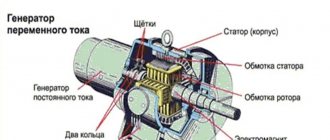
Transformer and mutual induction
If you place two coils in close proximity, for example, on the same core, then the phenomenon of mutual induction will be observed. Let's pass alternating current through the first, then its alternating flow will penetrate the turns of the second and an EMF will appear at its terminals.
This EMF will depend on the length of the wire, respectively, the number of turns, as well as on the value of the magnetic permeability of the medium. If they are simply placed next to each other, the EMF will be low, and if we take a core made of soft magnetic steel, the EMF will be much greater. Actually, this is how the transformer is designed.
Interesting: this mutual influence of the coils on each other is called inductive coupling.
Benefits and harms
The phenomenon of self-induction is something that most people experience every day without even realizing it. For example, the operating principle of fluorescent tubular lamps is based precisely on the phenomenon of self-induction. This phenomenon can also be observed in the ignition circuit of gasoline-powered vehicles. This is possible due to the presence of an inductor and a chopper. So, at the moment when current passes through the coil, the breaker breaks the power supply circuit of the coil, as a result of which an EMF is formed, which further leads to the fact that a pulse of more than 10 kV is supplied to the spark plugs.
The phenomenon of self-induction also brings benefits by removing unnecessary pulsation, frequencies or various noises in music speakers or other audio equipment. It is on this that the work of various “noise” filters is based.
However, self-induction can bring not only benefits, but also significant harm. Especially often it damages various switches, knife switches, sockets and other devices that break the electrical circuit. Its negative impact on electrical appliances can be seen with the naked eye: a spark in the socket at the moment of pulling out the plug or a working hair dryer is a manifestation of resistance to changes in current strength.
It will be interesting➡ What is an RCD?
This is why light bulbs most often burn out when the lights are turned off, and not vice versa. This is due to the fact that resistance leads to contact burnout and the accumulation of current circuits in various electrical appliances, which in turn represents a rather serious technical problem.
Inductance and self-induction are unfamiliar terms that many people encounter on a daily basis. And if the first term is a physical quantity denoting the ability of a conductor to prevent a change in voltage, then the second explains the appearance of induced emf in the same conductor.
Formulas
The circuit's own magnetic flux (F) is directly proportional to the inductance (L) of this circuit and the amount of current in it (i). This dependence is expressed by the formula: Ф = L×i. The proportionality coefficient L is usually called the self-inductance coefficient or simply the circuit inductance.
In this case, the inductance of the circuit depends on its geometry, the area of the plane limited by the coil and the magnetic permeability of the environment. But this coefficient does not depend on the current strength in the circuit. If the shape, linear dimensions and magnetic permeability do not change, then the formula is used to determine the value of the inductive emf:
where Esamoind. – EMF of self-induction, Δi – change in current strength over time Δt.
Magnetic field energy
Magnetic field energy of the inductance circuit L
with current strength
I
\(~W_m = \dfrac{L \cdot I^2}{2}.\)
Since \(~\Phi = L \cdot I\), the energy of the magnetic field of the current (coil) can be calculated knowing any two of the three values ( Φ, L, I
):
\(~W_m = \dfrac{L \cdot I^2}{2} = \dfrac{\Phi \cdot I}{2}=\dfrac{\Phi^2}{2L}.\)
Magnetic energy field contained in a unit volume of space occupied by the field is called volumetric energy density
magnetic field:
\(\omega_m = \dfrac{W_m}{V}.\)
*Derivation of the formula
1 output.
L to a current source
.
Let the current increase uniformly from zero to a certain value I
(ΔI
=
I
)
.
The self-induction emf will be equal to \(E_{si} =-L \cdot \dfrac{\Delta I}{\Delta t} = -L \cdot \dfrac{I}{\Delta t}.\)
For a given period of time Δ t
charge is transferred through the circuit
\(\Delta q = \left\langle I \right \rangle \cdot \Delta t,\)
where \(\left \langle I \right \rangle = \dfrac{I}{2}\) — average current value over time Δ t
with its uniform increase from zero
to I.
Current strength in a circuit with inductance L
reaches its value not instantly, but over a certain finite period of time
Δt
.
In this case, a self-inductive emf Esi appears in the circuit, preventing the increase in current strength. Consequently, when the current source is closed, it does work against the self-inductive emf, i.e. \(A = -E_{si} \cdot \Delta q.\)
The work expended by the source to create a current in the circuit (without taking into account thermal losses) determines the magnetic field energy stored by the current-carrying circuit. That's why
\(W_m = A = L \cdot \dfrac{I}{\Delta t} \cdot \dfrac{I}{2} \cdot \Delta t = \dfrac{L \cdot I^2}{2}.\ )
2 output
.
If the magnetic field is created by the current passing in the solenoid, then the inductance and modulus of the magnetic field of the coil are equal
\(~L = \mu \cdot \mu_0 \cdot \dfrac {N^2}{l} \cdot S, \,\,\, ~B = \dfrac {\mu \cdot \mu_0 \cdot N \cdot I}{l}\)
or
\(I = \dfrac {B \cdot l}{\mu \cdot \mu_0 \cdot N}.\)
Substituting the resulting expressions into the formula for the magnetic field energy, we obtain
\(~W_m = \dfrac {1}{2} \cdot \mu \cdot \mu_0 \cdot \dfrac {N^2}{l} \cdot S \cdot \dfrac {B^2 \cdot l^2} {(\mu \cdot \mu_0)^2 \cdot N^2} = \dfrac {1}{2} \cdot \dfrac {B^2}{\mu \cdot \mu_0} \cdot S \cdot l. \)
Since \(~S \cdot l = V\) is the volume of the coil, the magnetic field energy density is equal to
\(\omega_m = \dfrac {B^2}{2\mu \cdot \mu_0},\)
where in
is the magnetic field induction module, μ is the magnetic permeability of the medium, μ0 is the magnetic constant.
Basic formulas of the section “Electromagnetic induction”
Algorithm for solving problems on the topic “Electromagnetic induction”:
1. Carefully read the conditions of the problem. Establish the reasons for the change in the magnetic flux penetrating the circuit.
2. Write down the formula:
- law of electromagnetic induction;
- induced emf in a moving conductor, if the problem considers a progressively moving conductor; If the problem considers an electrical circuit containing a current source and an induced emf arising in one of the sections, caused by the movement of a conductor in a magnetic field, then you first need to determine the magnitude and direction of the induced emf. After this, the problem is solved by analogy with problems for calculating a direct current circuit with several sources.
3. Write down an expression for the change in magnetic flux and substitute it into the formula for the law of electromagnetic induction.
4. Write down all additional conditions mathematically (most often these are the formulas of Ohm’s law for a complete circuit, Ampere force or Lorentz force, formulas of kinematics and dynamics).
5. Solve the resulting system of equations for the desired value.
6. Check the solution.
Loop inductance. Self-induction
An electric current flowing in a closed circuit creates a magnetic field around itself, the induction of which, according to the Biot-Savart-Laplace law (see (110.2)), is proportional to the current. The magnetic flux Ф associated with the circuit is therefore proportional to the current I
in the outline:
Ф=LI,
(126.1)
where the proportionality coefficient L
called
loop inductance.
When the current in the circuit changes, the magnetic flux associated with it will also change; therefore, an emf will be induced in the circuit. Emergence of e.m.f. Induction in a conducting circuit when the current strength changes in it is called self-induction.
From expression (126.1) the henry
(H): 1 H is the inductance of such a circuit, the self-induction magnetic flux of which at a current of 1 A is equal to 1 Wb:
1 Gn=1 Wb/A=1B•s/A.
Let's calculate the inductance of an infinitely long solenoid. According to (120.4), the total magnetic flux through the solenoid
(flux linkage) is equal to m0m( N2I/l
)
S.
Substituting this expression into formula (126.1), we obtain
i.e. the inductance of the solenoid depends on the number of turns of the solenoid N,
its length
l
, area S and magnetic permeability m of the substance from which the solenoid core is made.
It can be shown that the inductance of a circuit in the general case depends only on the geometric shape of the circuit, its size and the magnetic permeability of the environment in which it is located. In this sense, the inductance of the circuit is an analogue of the electrical capacitance of a solitary conductor, which also depends only on the shape of the conductor, its dimensions and the dielectric constant of the medium (see §93).
Applying Faraday's law to the phenomenon of self-induction (see (123.2)), we obtain that the emf. self-induction
If the circuit is not deformed and the magnetic permeability of the medium does not change (later it will be shown that the last condition is not always satisfied), then L
=const and
where the minus sign, due to Lenz's rule, shows that the presence of inductance in the circuit slows down the change
current in it.
If the current increases over time, then
dI/dt>0 and ξs<0, i.e. self-induction current
is directed towards the current caused by an external source and inhibits its increase. If the current decreases over time, then dI/dt<0 and ξ s>
0
,
i.e. induction
the current has the same direction as the decreasing current in the circuit and slows down its decrease. Thus, the circuit, having a certain inductance, acquires electrical inertia, which consists in the fact that any change in current is inhibited the more strongly, the greater the inductance of the circuit.
$ 127. Currents when opening and closing a circuit
With any change in current strength in a conducting circuit, an emf occurs. self-induction, as a result of which additional currents appear in the circuit, called extra-self-induction currents.
Extra currents of self-induction, according to Lenz's rule, are always directed so as to prevent changes in the current in the circuit, that is, they are directed opposite to the current created by the source. When the current source is turned off, the extra currents have the same direction as the weakening current. Consequently, the presence of inductance in the circuit slows down the disappearance or establishment of current in the circuit.
Let us consider the process of turning off the current in a circuit containing a current source with an emf. ξ, resistor with resistance R
and a coil with inductance
L.
Under the influence of external emf. direct current flows in the circuit
I
0=ξ/
R
(we neglect the internal resistance of the current source).
At time t=
0turn off the current source.
The current through the inductor L
will begin
self-induction ξ s=-LdI/dt,
which, according to Lenz’s rule, prevents a decrease in current.
At each moment of time, the current in the circuit is determined by Ohm’s law I=ξs/R,
or
IR=-LdI/dt.
(127.1)
Dividing the variables in expression (127.1), we obtain d I/I
=
-(R/L)dt.
Integrating
this is the equation for I
(from I0 to I) and
t
(from 0 to t), we find ln(I/I0)=-
Rt/L,
or
where t=L/R is a constant called relaxation time.
From (127.2) it follows that t is the time during which the current strength decreases by e times.
Thus, in the process of turning off the emf source. the current decreases according to the exponential law (127.2) and is determined by the curve 1
in Fig. 183. The greater the inductance of the circuit and the lower its resistance, the greater m and, therefore, the slower the current in the circuit decreases when it opens.
When the circuit is closed, in addition to the external emf ξ, an emf arises. self-induction
ξs=-LdI/dt,
obstructive, according to
Lenz's rule, increasing current. According to Ohm's law, IR=ξ+ξs, or
IR
=
ξ-LdI/dt
.
By introducing a new variable u=IR-ξ,
Let's transform this equation to the form
du/u=-dt/t,
where 1 -
relaxation time.
At the moment of closure (t=0) the current strength I
=0 and
u=-ξ.
Therefore, integrating over u (from -ξ to
IR - ξ)
and t (from 0 to t).
we find ln( IR
-ξ)/-ξ
=-t/t,
or
where I
0=ξ
/R
- steady current (at t®¥)
Thus, in the process of turning on the emf source. the increase in current in the circuit is given by function (127.3) and determined by the curve 2
in Fig.
183. The current strength increases from the initial value I
=0 and asymptotically tends to the steady value
I
0
=ξ/R.
The rate of current increase is determined by the same relaxation time t
= L/R
as the current decrease. The establishment of current occurs the faster, the lower the inductance of the circuit and the greater its resistance.
Let's estimate the value of emf. self-induction ξ s,
arising with an instantaneous increase in the resistance of the DC circuit from
R
0 to
R.
Let us assume that we open the circuit when a steady current
I
0 = ξ/R0 flows in it.
When the circuit is opened, the current changes according to formula (127.2). Substituting the expression for I
0 and t into it, we get
E.m.f. self-induction
i.e., with a significant increase in circuit resistance (R/R
0
>>
1
)
having high inductance, emf. self-induction can be many times higher than the emf. current source included in the circuit. Thus, it is necessary to take into account that a circuit containing inductance cannot be abruptly opened, since this (the occurrence of significant self-induction emf) can lead to insulation breakdown and failure of measuring instruments. If resistance is gradually introduced into the circuit, then the emf. self-induction will not reach large values.
Mutual induction
Consider two fixed contours (1 to 2),
located quite close to each other (Fig. 184).
1
flows
in circuit 1 ,
then
1.
Symbol
Let's start through F21 with that part of the flow that penetrates circuit
2.
Then
Ф21= L
21/
I
1, (128.1)
where L
21 - proportionality coefficient.
If current I
1 changes, then
an emf is induced
ξi2 ,
which, according to Faraday’s law (see (123.2)), is equal and opposite in sign to the rate of change of the magnetic flux Ф21 created by the current in the first circuit and penetrating the second:
Similarly, when flowing in the circuit 2
current I2 magnetic flux (its field is shown in Fig. 184 by a dashed line) penetrates the first circuit.
If Ф12 is part of this flow penetrating circuit 1 ,
then
Ф12 = L
12
I
2.
If current I
2 changes, then
an emf is induced
1. ξi1 ,
which is equal and opposite in sign to the rate of change of the magnetic flux Ф12 created by the current in the second circuit and penetrating the first:
The phenomenon of emf occurrence in one of the circuits when the current strength in the other changes is called mutual induction.
The proportionality coefficients
L
21 and
L
12 are called
the mutual inductance of the circuits.
Calculations, confirmed by experience, show that
l
21 and
L
12 are equal to each other, i.e.
L
I2 =
L
2I. (128.2)
L
coefficients
12 and
L
21 depend on the geometric shape, size, relative position of the circuits and on the magnetic permeability of the medium surrounding the circuits. The unit of mutual inductance is the same as for inductance, the henry (H).
Let's calculate the mutual inductance of two coils wound on a common toroidal core. This case is of great practical importance (Fig. 185). Magnetic induction of the field created by the first coil with the number of turns N
1, current
I
1 and magnetic permeability m of the core, according to (119.2),
B=m
0
mN
1
I
1
/l,
where
l
is the length of the core
along the midline. Magnetic flux through one turn of the second coil Ф2=BS=m0m( N
1
I
1/
l
)S Then the total magnetic flux (flux linkage) through the secondary winding containing
N2
turns,
The flow y is created by the current I
1
,
therefore, according to (128.1), we obtain
If we calculate the magnetic flux created by the coil 2
through coil
1
, then for
L
12 we obtain an expression in accordance with formula (128.3). Thus, the mutual inductance of two coils wound on a common toroidal core is
Transformers
The operating principle of transformers used to increase or decrease alternating current voltage is based on the phenomenon of mutual induction. Transformers were first designed and put into practice by the Russian electrical engineer P. N. Yablochkov (1847-1894) and the Russian physicist I. F. Usagin (1855-1919). The schematic diagram of the transformer is shown in Fig. 186.
Primary and secondary coils (windings), having n
1 and
N
2 turns, mounted on a closed iron core.
Since the ends of the primary winding are connected to an alternating voltage source with emf. ξ1 ,
I
1
arises in it ,
creating an alternating magnetic flux F in the transformer core, which is almost completely localized in the iron core and, therefore, almost completely penetrates the turns of the secondary winding. A change in this flux causes the appearance of an emf in the secondary winding. mutual induction, and in the primary - emf. self-induction.
Current I
1 of the primary winding is determined according to Ohm's law:
where R
1—resistance of the primary winding.
The voltage drop I
1
R
1 across resistance R
1
in rapidly varying fields is small compared to each of the two emfs, therefore
E.m.f. mutual induction arising in the secondary winding,
Comparing expressions (129.1) and (129.2), we find that the emf.
, arising in the secondary winding,
where the minus sign indicates that the emf. in the primary and secondary windings are opposite in phase.
Number of turns ratio N
2
/N
1
,
showing how many times the emf.
In the secondary winding of the transformer there is more (or less) than in the primary winding, called the transformation ratio
Neglecting energy losses, which in modern transformers do not exceed 2% and are associated mainly with the release of Joule heat in the windings and the appearance of eddy currents, and applying the law of conservation of energy, we can write that the current powers in both windings of the transformer are almost the same:
ξ
2
I
2
»ξ
1
I
1
,
from where, taking into account relation (129.3), we find
ξ2/ξ1= I
1/
I
2 =
N
2/
N
1,
that is, the currents in the windings are inversely proportional to the number of turns in these windings.
If N
2
/N
1>1, then we are dealing with
a step-up transformer that increases
and reducing current (used, for example, to transmit electricity over long distances, since in this case the losses due to Joule heat, proportional to the square of the current strength, are reduced);
if N2/N
1<1
,
then we are dealing with
a step-down transformer that
reduces the emf. and increasing current (used, for example, in electric welding, since it requires high current at low voltage).
We considered transformers with only two windings. However
transformers used in radio devices have 4-5 windings with different operating voltages. A transformer consisting of one winding is called an autotransformer.
In the case of a step-up autotransformer, the emf. is supplied to part of the winding, and the secondary emf. is removed from the entire winding. In a step-down autotransformer, the mains voltage is supplied to the entire winding, and the secondary emf. is removed from part of the winding.
Magnetic field energy
A conductor through which electric current flows is always surrounded by a magnetic field, and the magnetic field appears and disappears along with the appearance and disappearance of the current. A magnetic field, like an electric field, is a carrier of energy. It is natural to assume that the energy of the magnetic field is equal to the work expended by the current to create this field.
Consider a circuit with inductance L,
through which current
I
.
A magnetic flux is coupled to this circuit (see (126.1)) Ф = LI
, and when the current changes by d
I,
the
magnetic flux changes by dФ =
L
d
I. However, to change the magnetic flux by an amount dФ (see § 121), it is necessary to do work d A
=
I
dФ =
LI
d
I.
Then the work to create the magnetic flux Ф will be equal to
Therefore, the energy of the magnetic field associated with the circuit is
W=LI2/2.
(130.1)
The study of the properties of alternating magnetic fields, in particular the propagation of electromagnetic waves, provided evidence that the energy of the magnetic field is localized in space. This corresponds to the concepts of field theory.
The energy of a magnetic field can be represented as a function of the quantities characterizing this field in the surrounding space. To do this, consider a special case - a uniform magnetic field inside a long solenoid. Substituting expression (126.2) into formula (130.1), we obtain
Since I=Вl/
(m0mN) (see (119.2)) and
B=m
0
mH
(see (109.3)), then
where Sl
=
V is
the volume of the solenoid.
The magnetic field of the solenoid is uniform and concentrated inside it, therefore the energy (see (130.2)) is contained in the volume of the solenoid and is distributed in it with a constant volume density
Expression (130.3) for the volumetric energy density of a magnetic field has a form similar to formula (95.8) for the volumetric energy density of an electrostatic field, with the difference that electrical quantities are replaced in it by magnetic ones. Formula (130.3) was derived for a homogeneous field, but it is also valid for inhomogeneous fields. Expression (130.3) is valid only for media for which the dependence B
linear
from i.e. it applies only to para- and diamagnetic materials
Vortex electric field
From Faraday's law ξ=dФ/dt
it follows that
any
change
The magnetic induction flow coupled to the circuit leads to the emergence of an electromotive force of induction and, as a result, an induction current appears. Consequently, the occurrence of emf. electromagnetic induction is also possible in a stationary circuit located in an alternating magnetic field. However, the e.m.f. in any circuit occurs only when external forces act on the current carriers in it - forces of non-electrostatic origin. Therefore, the question arises about the nature of external forces in this case.
Experience shows that these extraneous forces are not associated with either thermal or chemical processes in the circuit; their occurrence also cannot be explained by Lorentz forces, since they do not act on stationary charges. Maxwell hypothesized that any alternating magnetic field excites an electric field in the surrounding space, which
and is the cause of the occurrence of induced current in the circuit. According to Maxwell's ideas, the circuit in which the emf appears plays a secondary role, being a kind of only a “device” that detects this field.
So, according to Maxwell, a time-varying magnetic field generates an electric field E B
, the circulation of which, according to (123.3),
where E Bl
— projection of the vector
E
B onto the direction d
l
.
Substituting the expression into formula (137.1), we obtain
If the surface and contour are stationary, then the operations of differentiation and integration can be swapped. Hence,
where the partial derivative symbol emphasizes the fact that the integral is
function only of time.
According to (83.3), the circulation of the electrostatic field strength vector (let’s denote it e
q) along any closed contour is equal to zero:
Comparing expressions (137.1) and (137.3), we see that between the fields under consideration ( E
B and
e
q) there is a fundamental difference: the circulation of the vector
E
B, unlike the circulation of the vector
e
q, is not zero.
Consequently, the electric field E
B excited by a magnetic field, like the magnetic field itself, is a vortex
Bias current
According to Maxwell, if any alternating magnetic field excites a vortex electric field in the surrounding space, then the opposite phenomenon should also exist: any change in the electric field should cause the appearance of a vortex magnetic field in the surrounding space. To establish quantitative relationships between a changing electric field and the magnetic field it causes, Maxwell introduced the so-called displacement current into consideration.
Consider an alternating current circuit containing a capacitor (Fig. 196). There is an alternating electric field between the plates of a charging and discharging capacitor, therefore, according to Maxwell, through the capacitor
Displacement currents “flow”, and in those areas where there are no conductors.
Let us find a quantitative relationship between the changing electric and the magnetic fields it causes. According to Maxwell, an alternating electric field in a capacitor at each moment of time creates such a magnetic field as if there were a conduction current between the plates of the capacitor equal to the current in the supply wires. Then we can say that conduction currents ( I
) and displacements (
I
cm) are equal:
I
cm =
I
. Conduction current near the capacitor plates
(surface charge density s on the plates is equal to the electrical displacement D
in the capacitor (see (92.1)).
The integrand in (138.1) can be considered a special case of the scalar product ( d D
/
d
t)d
S
when
d D
/
d
t and d
S
are mutually parallel. Therefore, for the general case we can write
Comparing this expression with I
=
I
cm = (see (96.2)), we have
Expression (138.2) was called by Maxwell the displacement current density.
Let's consider what is the direction of the conduction and displacement current density vectors j
and
j
see. When charging a capacitor (Fig. 197, a) through the conductor connecting the plates, the current flows from the right plate to the left; the field in the capacitor increases, vector D increases with time;
therefore, d D
/
d
t>0, i.e.
vector d D
/
d
t
directed in the same direction as D. The figure shows that the directions of the vectors
d D
/
d
t and
j
coincide.
When the capacitor is discharged (Fig. 197, b) through the conductor connecting the plates, the current flows from the left plate to the right; the field in the capacitor is weakened, vector D
decreases with time;
therefore, d D
/
d
t<0, i.e. vector
at
d D
/
d
t is directed opposite to the vector
D. However, vector d D
/
d
t directed again like this
same as vector j
.
From the examples discussed, it follows that the direction of vector j
, and therefore vector
j
cm, coincides
With
direction of the vector
d D
/
d
t,
as follows from formula (138.2).
We emphasize that of all the physical properties inherent in conduction current, Maxwell attributed only one to displacement current - the ability to create a magnetic field in the surrounding space. Thus, the displacement current (in a vacuum or substance) creates a magnetic field in the surrounding space (the induction lines of the magnetic fields of the displacement currents when charging and discharging a capacitor are shown in Fig. 197 by a dashed line).
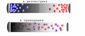
In dielectrics, the displacement current consists of two terms. Since, according to (89.2), D
=e0
E
+
P
, where
E
is the electrostatic field strength, and
P
is the polarization (see § 88), then the displacement current density
where e0 d E
/
d
t
—displacement current density
in vacuum, d P
/
d
t
- polarization current density -
current caused by the ordered movement of electric charges in a dielectric (displacement of charges in non-polar molecules or rotation of dipoles in polar molecules). Excitation of a magnetic field by polarization currents is legitimate, since polarization currents by their nature do not differ from conduction currents. However, the same as the other
(e0 d E
/
d
t),
part of the bias current density (e0 d E
/
d
t),
not associated with the movement of charges, but due only
a change in the electric field over time also excites a magnetic field, which is
a fundamentally new statement
by Maxwell. Even in a vacuum, any change in time of the electric field leads to the appearance of a magnetic field in the surrounding space.
It should be noted that the name “displacement current” is conditional, or rather, historically developed, since the displacement current is inherently an electric field that changes over time. Displacement current therefore exists not only in vacuum or dielectrics, but also inside conductors through which alternating current flows. However, in this case it is negligible compared to the conduction current. The presence of displacement currents was confirmed experimentally by the Soviet physicist A. A. Eikhenvald, who studied the magnetic field of the polarization current, which, as follows from (138.3), is part of the displacement current.
Maxwell introduced the concept of total current,
equal to the sum of conduction currents (as well as convection currents) and displacement.
Total current density
jtotal=j+ d D
/
d
t.
By introducing the concepts of displacement current and total current, Maxwell took a new approach to considering the closed circuits of alternating current circuits. The total current in them is always closed, that is, at the ends of the conductor only the conduction current is interrupted, and in the dielectric (vacuum) between the ends of the conductor there is a displacement current that closes the conduction current.
Maxwell generalized the theorem on the circulation of the vector H
(see (133.10)), introducing into its right side the total current
I
total= through the surface
S
stretched over a closed contour
L.
Then
the generalized theorem on the circulation of the vector H
will be written in the form
Expression (138.4) is always true, as evidenced by the complete correspondence between theory and experience.
Law of Electromagnetic Induction
The law of electromagnetic induction (Faraday's law) sounds like this:
The induced emf in a closed loop is equal and opposite in sign to the rate of change of the magnetic flux through the surface bounded by the loop.
Mathematically it can be described by the formula:
| Faraday's law Ɛi — induced emf [V] ΔФ/Δt — rate of change of magnetic flux [Wb/s] |
The “–” sign in the formula allows you to take into account the direction of the induction current. The induced current in a closed circuit is always directed so that the magnetic flux of the field created by this current through the surface bounded by the circuit would reduce those changes in the field that caused the appearance of the induced current.
If the circuit consists of N turns (that is, it is a coil), then the induced emf will be calculated as follows.
| Faraday's law for a circuit of N turns Ɛi — induced emf [V] ΔФ/Δt — rate of change of magnetic flux [Wb/s] N - number of turns [-] |
The strength of the induction current in a closed conductive circuit with resistance R:
| Ohm's law for a conductive circuit Ɛi — induced emf [V] I - induction current strength [A] R - circuit resistance [Ohm] |
If a conductor of length l moves with speed v in a constant uniform magnetic field with induction B the emf of electromagnetic induction is equal to:
| Induction emf for a moving conductor Ɛi — induced emf [V] B—magnetic induction [T] v—conductor speed [m/s] l - conductor length [m] |
The occurrence of induced emf in a conductor moving in a magnetic field is explained by the action of the Lorentz force on free charges in moving conductors. The Lorentz force plays the role of an external force in this case.
A conductor moving in a magnetic field through which an induced current flows experiences magnetic braking. The total work done by the Lorentz force is zero.
The amount of heat in the circuit is released either due to the work of an external force, which maintains the speed of the conductor unchanged, or due to a decrease in the kinetic energy of the conductor.
A change in the magnetic flux penetrating a closed circuit can occur for two reasons:
- due to movement of the circuit or its parts in a time-constant magnetic field. This is the case when conductors, and with them free charge carriers, move in a magnetic field
- due to changes in time of the magnetic field with a stationary circuit. In this case, the occurrence of induced emf can no longer be explained by the action of the Lorentz force. The phenomenon of electromagnetic induction in stationary conductors, which occurs when the surrounding magnetic field changes, is also described by Faraday's formula
Thus, the phenomena of induction in moving and stationary conductors proceed in the same way, but the physical reason for the occurrence of induction current turns out to be different in these two cases:
- in the case of moving conductors, the induced emf is due to the Lorentz force
- in the case of stationary conductors, the induced emf is a consequence of the action on free charges of the vortex electric field that occurs when the magnetic field changes.
Magnetic flux
Before we talk about electromagnetic induction and self-induction, we need to define the essence of magnetic flux.
Imagine that you picked up a hoop and went outside into the rain. Streams of water will pass through the hoop.
If you hold the hoop horizontally, a lot of water will pass through it. And if you start to turn it, it’s already smaller, because it is not located at a right angle to the vertical.
Now let's place the hoop vertically - not a single drop will pass through it (unless the wind blows, of course).
The magnetic flux is very similar to the flow of water passing through a hoop, only we count the magnitude of the magnetic field passed through the area, not the rain.
The magnetic flux through the area S of the circuit is a scalar physical quantity equal to the product:
- magnetic induction vector module B ,
- surface area S , which the flow penetrates,
- and the cosine of the angle α between the direction of the magnetic induction vector and the normal vector (perpendicular to the plane of a given surface).
| Magnetic flux Ф - magnetic flux [Wb] B —magnetic induction [T] S – area of the penetrated surface [m2] n — normal vector (perpendicular to the surface) [-] |
Magnetic flux can be visualized as a value proportional to the number of magnetic lines passing through a given area.
Depending on the angle α , the magnetic flux can be positive ( α < 90° ) or negative ( α > 90° ). If α = 90° , then the magnetic flux is 0.
You can change the magnetic flux by changing the area of the circuit, the field induction module, or the location of the circuit in the magnetic field (by rotating it).
In the case of a non-uniform magnetic field and a non-flat contour, the magnetic flux is found as the sum of the magnetic fluxes penetrating the area of each of the sections into which a given surface can be divided.
Lenz's rule
To determine the direction of the induced current, you need to use Lenz's rule.
Academically, this rule is as follows: the induced current excited in a closed loop when the magnetic flux changes is always directed in such a way that the magnetic field it creates prevents the change in the magnetic flux causing the induced current.
Let's try a little simpler: the coil in this case is a dissatisfied granny. They take away her magnetic flux - she is unhappy and creates a magnetic field, which this magnetic flux wants to take back.
They give her a magnetic flux, take it, they say, use it, and she’s like, “Why did I give up your magnetic flux!” and creates a magnetic field, which expels this magnetic flux.
How to use the power of self-induction in life:
Physics is nothing without practical application. The phenomenon of self-induction is actively used in everyday life. For example, an ignition coil is involved in the operation of a carburetor engine.
The ignition coil receives a charge of 12 V. The electrical circuit is terminated using a special breaker. This creates a strong spark that ignites the fuel. The car starts moving. In modern machines, the circuit breaks automatically, but the principle of self-induction remains the same.
Self-induction is also used in the operation of network filters. It helps smooth out voltage surges and fill gaps in the current supply. As a result, it is possible to eliminate noise, ripple and unnecessary frequencies.
Self-induction of the coil is used to ignite electrodes in gas-discharge light sources. When the starter is triggered, the contacts are broken, which causes a self-induced emf to arise in the coil. The lamp begins to perform its function due to a burst of energy.
Examples of use in practice
The phenomenon of self-induction has found wide practical application. Car enthusiasts know very well what an ignition coil is. Without it, the carburetor engine will not start.
This important node works as follows:
- An on-board voltage of 12 V is supplied to the coil with high inductance.
- The electrical circuit is abruptly interrupted by a special breaker.
- The accumulated energy of self-induction is supplied through high-voltage wires to the spark plug and forms a powerful spark at its electrodes.
- A spark discharge ignites the fuel mixture, driving the piston.
In modern cars, the circuit is broken by electronics, but the essence does not change - self-induction energy is still used to form a spark.
We have already mentioned network filters that use the phenomenon of self-induction. The RL chain reacts to any change in parameters. As it increases, it delays peak surges in time and fills gaps with its own eddy currents. Thus, the voltage in the electrical circuits is smoothed out.
In power supplies for electronic equipment, the following is removed in the same way:
- noises:
- pulsations;
- unwanted frequencies.
Self-induction of chokes is used in fluorescent lamps to ignite electrodes. After the starter is triggered, the contacts break, resulting in a self-inductive emf being induced in the inductor. The choke energy ignites an arc on the electrodes, and the fluorescent lamp begins to glow.
The examples listed demonstrate the useful application of self-induction. However, as always happens, induced emf can cause harm. When disconnecting the contacts of switches whose load is circuits with high inductance, arc discharges are possible. They destroy contacts, slow down the protection time, etc. In order to reduce the risk from the negative effects of self-induction, circuit breakers are equipped with arc suppression chambers.
In such cases, it is necessary to take measures to neutralize the energy of the self-induction EMF. An even greater need for dissipating self-induction energy arises in semiconductor switches that are sensitive to breakdowns.
In industry and energy, self-induction is a serious problem. When disconnecting loaded lines, the self-induction emf can reach life-threatening values. This requires additional costs for taking precautions. In particular, it is necessary to install devices on the lines that prevent the lightning-fast opening of the circuit.
Physics lesson “Self-induction. Inductance. Energy of the magnetic field of current" (grade 8)
Physics lesson plan “Self-induction. Inductance. Energy of the magnetic field of current" (grade 8)
Lesson topic: Self-induction. Inductance. Magnetic field energy.
Target:
Formation of the concept of the phenomenon of self-induction, its manifestation in electric current circuits. Application of self-induction in electrical devices.
Tasks:
Educational:
Repeat students’ knowledge about the phenomenon of electromagnetic induction, deepen it; on this basis, study the phenomenon of self-induction.
Educational:
Cultivate interest in the subject, hard work and the ability to carefully evaluate the answers of your comrades. Show the importance of cause-and-effect relationships in the cognition of phenomena.
Educational:
Development of students’ physical thinking, expansion of students’ conceptual apparatus, formation of skills to analyze information, draw conclusions from observations and experiments.
Lesson type:
lesson of learning new material.
Equipment:
Core inductor – demonstration, power supply, key, two 3.5 V bulbs, 100 ohm rheostat, 200 V neon bulb.
Experiences:
1) experience in observing the phenomenon of self-induction when closing a circuit; 2) experience in observing the phenomenon of self-induction when the circuit opens;
Lesson plan:
- Organizing time.
- Updating basic knowledge.
- Motivation.
- Learning new material.
- Consolidation.
- Homework.
During the classes
- Organizing time.
(1 min)
- Updating basic knowledge.
— What is called the phenomenon of electromagnetic induction?
-Which hypothesis of Faraday led to the discovery of electromagnetic induction?
-How did Faraday discover the phenomenon of electromagnetic induction?
-Under what conditions does induced current occur in the coil?
- What determines the direction of the induction current?
-What explains the repulsion of an aluminum ring when a magnet is inserted into it and the attraction to the magnet when it is removed from the ring?
— Why doesn’t a cut aluminum ring interact with a moving magnet?
— Formulate Lenz’s rule.
-How can you use Lenz’s rule to determine the direction of the induced current in a conductor?
3. Motivation.
The foundations of electrodynamics were laid by Ampere in 1820. Ampere's work inspired many engineers to design various technical devices, such as an electric motor (designed by B. S. Jacobi), a telegraph (S. Morse), and an electromagnet, which was designed by the famous American scientist Henry. While creating various electromagnets, in 1832 the scientist discovered a new phenomenon in electromagnetism - the phenomenon of self-induction. We will talk about this in this lesson.
4.Learning new material
.
Let's consider a special case of electromagnetic induction: the appearance of an induced current in a coil when the current strength in it changes.
To do this, we will carry out the experiment shown in the figure. Let's close the circuit with the key CL. Lamp L1 will light up immediately, and L2 will light up with a delay of approximately 1 s. The reason for the delay is as follows. According to the phenomenon of electromagnetic induction, induction currents arise in the rheostat and in the coil. They prevent the current I1 and I2 from increasing (this follows from Lenz’s rule and the right-hand rule). But in coil K the induction current will be significantly greater than in rheostat P, since the coil has a much larger number of turns and a core, that is, it has greater inductance than the rheostat.
In this experiment we observe the phenomenon of self-induction.
The phenomenon of self-induction consists in the occurrence of an induced current in a coil when the current strength in it changes. In this case, the resulting induction current is called self-induction current.
This phenomenon was discovered by Joseph Henry, almost simultaneously with the discovery of the phenomenon of electromagnetic induction by Faraday.
Self-induction when opening an electrical circuit and the energy of a magnetic field.
The appearance of a powerful induction current when the circuit is opened indicates that the magnetic field of the current in the coil has energy. It is by reducing the energy of the magnetic field that work is done to create an induction current. At this moment, the Ln lamp flashes, which, under normal conditions, lights up at a voltage of 200V. And this energy accumulated earlier, when the circuit was closed, when, due to the energy of the current source, work was done to overcome the self-induction current, which prevents an increase in the current in the circuit, and its magnetic field.
Inductance
- this is a value equal to the self-induction emf when the current in the conductor changes by 1 A in 1 s. The unit of inductance is henry (H). 1 H = 1 V • s/A. 1 henry is the inductance of a conductor in which a self-inductive emf of 1 volt occurs at a rate of change of current of 1 A/s. L is called inductance. Demonstration of various inductors used in radio engineering and electrical engineering. We use handouts for students to view. (inductors)
Fluorescent Lamp
– These are gas-discharge light sources. Their luminous flux is formed due to the glow of phosphors, which are exposed to ultraviolet radiation from the discharge. Its visible glow usually does not exceed 1-2%. Fluorescent lamps (FL) are widely used in lighting various types of premises. Their luminous output is many times greater than that of conventional incandescent lamps. A device called a starter is used as a switch. The starter is a small glow discharge lamp. A glass flask is filled with an inert gas (neon or a helium-hydrogen mixture) and placed in a metal or plastic case. When you turn on the circuit voltage, it will be completely applied to the starter. The starter electrodes are open and a glow discharge occurs in it. A small current (20-50 mA) will flow in the circuit. This current heats the bimetallic electrodes, and when they bend, they close the circuit, and the glow discharge in the starter will stop. After the lamp is ignited, a current will be established in the circuit equal to the rated operating current of the lamp. This current will cause such a voltage drop across the inductor that the voltage across the lamp will become approximately equal to half the rated network voltage. Since the starter is connected in parallel with the lamp, the voltage on it will be equal to the voltage on the lamp, and due to the fact that it is not enough to ignite the glow discharge in the starter, its electrodes will remain open when the lamp burns.
5. Consolidation.
1. What phenomenon was studied in the experiment. 2. What is the phenomenon of self-induction? 3. Can a self-induction current occur in a straight conductor carrying current? If not, explain why; if yes, then under what conditions. 4. By reducing what energy was the work done to create an induction current when the circuit was opened?
5. What facts prove that a magnetic field has energy?
6. What is inductance?
7. What is the SI unit of inductance and what is it called?
8. What is a choke and why is it needed when operating a fluorescent lamp?
Task 1.
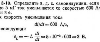
What is the inductance of the coil if, with a gradual change in the current strength in it from 5 to 10 A in 0.1 s, a self-inductive emf equal to 20 V arises?
| Given: I1=5 A I2=10 A t=0.1 s ε=20 V | L= | [L]== Gn {L}===0.4 Answer: 0.4 Gn |
| L — ? |
Task 2.
Find the inductance of the conductor in which, with a uniform change in current strength by 2 A for 0.25 s, a self-inductive emf of 20 mV is excited.
6. Homework.
Read §23 Questions §23, page 101. If desired, prepare messages on the topics: “The use of inductors in electrical engineering”, “The use of fluorescent lamps”, “The fight against self-induction in electrical engineering”.
What is important to remember about inductance
As already noted, the inductance of the circuit can change depending on its geometry, coverage, and magnetic characteristics of the environment. These rules also apply to the throttle. Its inductance can vary depending on the diameter and intensity of the winding. The inductance value will also increase when using a ferromagnetic core.
The degree of inductance will vary according to how strongly the transmitter, the role of which is played by the spirals, resists the electrical impulse. With high inductance and a quick stop of its circuit, a strong surge of EMF will occur.
Inductance is expressed using the Henry unit. 1H corresponds to an emf of 1V at a rate of current change of 1A per second.
The inductance value helps determine how much energy is released due to the magnetic field during self-induction. The energy can be calculated using the formulation Wm = LI2 / 2.
Self-induction and inertia
The phenomenon of self-induction is easier to understand by drawing an analogy with inertia in mechanics. Inertia leads to the fact that under the influence of force a body does not instantly acquire speed, but gradually. The body cannot be instantly slowed down, no matter how great the braking force. In the same way, due to self-induction, when the circuit is closed, the current strength does not immediately acquire a certain value, but increases gradually. By turning off the source, we do not stop the current immediately. Self-induction maintains it for some time, despite the resistance of the circuit.
To increase the speed of a body, according to the laws of mechanics, work must be done. When braking, the body itself does work. In the same way, to create a current, work must be done against the vortex electric field, and when the current disappears, this field does positive work.
What is an inductor
What do you mean by the word “reel”? Well... this is probably some kind of “fig” on which threads, fishing line, rope, whatever! An inductor coil is exactly the same thing, but instead of a thread, fishing line or anything else, ordinary copper wire in insulation is wound there.
The insulation can be made of clear varnish, PVC insulation, or even fabric. The trick here is that although the wires in the inductor are very close to each other, they are still isolated from each other. If you wind inductor coils with your own hands, do not under any circumstances even think about using ordinary bare copper wire!
Series and parallel connection of inductors
When inductors are connected in series, their total inductance will be equal to the sum of the inductances.
And with a parallel connection we get this:
When connecting inductors, the rule must be followed so that they are spatially separated on the board. This is because if they are close to each other, their magnetic fields will influence each other and therefore the readings of the inductances will be incorrect. Do not place two or more toroidal coils on one iron axis. This may result in incorrect total inductance readings.
Types of Inductors
Inductors are divided mainly into two classes: with a magnetic and non-magnetic core. Below in the photo is a coil with a non-magnetic core.
But where is her core? Air is a non-magnetic core :-). Such coils can also be wound on some cylindrical paper tube. Inductance coils with a non-magnetic core are used when the inductance does not exceed 5 millihenry.
And here are the inductors with a core:
Cores made of ferrite and iron plates are mainly used. The cores increase the inductance of the coils significantly. Cores in the form of a ring (toroidal) allow you to obtain higher inductance than just cylinder cores.
For medium inductance coils, ferrite cores are used:
Coils with high inductance are made like a transformer with an iron core, but with one winding, unlike a transformer.
Literature
- Aksenovich L. A. Physics in secondary school: Theory. Tasks. Tests: Textbook. allowance for institutions providing general education. environment, education / L. A. Aksenovich, N. N. Rakina, K. S. Farino; Ed. K. S. Farino. - Mn.: Adukatsiya i vyhavanne, 2004. - P. 351-355, 432-434.
- Zhilko V.V. Physics: textbook. allowance for 11th grade. general education institutions with Russian language Training with a 12-year period of study (basic and advanced levels) / V.V. Zhilko, L.G. Markovich. — Mn.: Nar. Asveta, 2008. - pp. 183-188.
- Myakishev, G.Ya. Physics: Electrodynamics. 10-11 grades : textbook for in-depth study of physics / G.Ya. Myakishev, A.3. Sinyakov, V.A. Slobodskov. - M.: Bustard, 2005. - P. 417-424.
induced emf
Let us understand in detail what the concept of induced emf is. When a conductor is placed in a magnetic field and moves with the intersection of field lines, an electromotive force called induced emf appears in the conductor. It also occurs if the conductor remains stationary, and the magnetic field moves and intersects the conductor with lines of force.
When the conductor where the EMF occurs is closed to the external circuit, due to the presence of this EMF, an induced current begins to flow through the circuit. Electromagnetic induction involves the phenomenon of inducing an EMF in a conductor at the moment it is crossed by magnetic field lines.
Electromagnetic induction is the reverse process of transforming mechanical energy into electric current. This concept and its laws are widely used in electrical engineering; most electric machines are based on this phenomenon.
EMF in everyday life and units of measurement
Other examples are found in the practical life of any ordinary person. This category includes such familiar things as small batteries, as well as other miniature batteries. In this case, the working EMF is formed due to chemical processes occurring inside constant voltage sources. When it occurs at the terminals (poles) of the battery due to internal changes, the element is completely ready for operation. Over time, the EMF decreases slightly, and the internal resistance increases noticeably.
As a result, if you measure the voltage on a AA battery that is not connected to anything, you see the normal 1.5V (or so), but when a load is connected to the battery, let’s say you installed it in some device, it does not work. Why? Because if we assume that the voltmeter’s internal resistance is many times higher than the internal resistance of the battery, then you measured its EMF. When the battery began to supply current to the load at its terminals, it became not 1.5V, but, say, 1.2V - the device did not have enough voltage or current for normal operation.
Calculation of EMF.
It was precisely these 0.3 V that dropped on the internal resistance of the galvanic element. If the battery is very old and its electrodes are destroyed, then there may be no electromotive force or voltage at all at the battery terminals - i.e. zero. A very small electromotive force is induced within the receiver antenna, which is then amplified by special cascades, and we receive our television, radio and even Wi-Fi signal.
Self-induction and transient processes in electrical circuits
The inductance of an electric stove or incandescent light bulb is very small, and the current in these electrical appliances, when turned on and off, appears or disappears almost instantly. The inductance of the electric motor is high, and it “goes into operation” within a few minutes.
If you turn off the current in a large electromagnet with a large induction value, allowing a high rate of decrease in the current, then a spark flashes between the contacts of the switch, and in the case of a large current, a voltaic arc may light up. This is a dangerous phenomenon, therefore, in circuits with high inductance, the current is reduced gradually using a rheostat (an element with variable electrical resistance).
Safely shutting off power is a serious issue. All switches are subject to “shock loads” that arise due to the self-inductive emf when the current is turned off, and the switches “spark.” For each type of switch, the maximum current value that can be switched is indicated. If the current exceeds the permissible value, an electric arc may flash in the switch.
In hazardous industries, coal mines, and petroleum product storage facilities, simple sparking of switches is unacceptable. Explosion-proof switches are used here, reliably protected by a sealed plastic housing. The price of such switches is tens of times higher than ordinary ones - this is a necessary payment for safety.
The interaction of electric and magnetic fields is the cause of self-induction
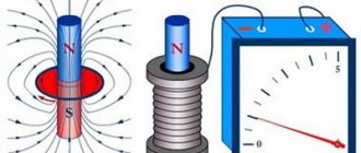
Electric and magnetic fields are interrelated: an electric current or a changing electric field creates a magnetic field.
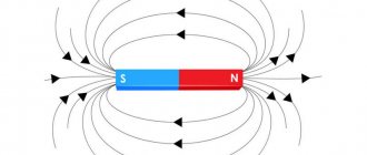
In turn, the changing magnetic field creates an electric field.
Let us consider the processes in a conducting circuit when the electric current in it changes (for example, it is turned on or off).
- An emf is induced in a conductor placed in a changing magnetic field.
- If the magnitude of the electric current changes in a conductor, a changing magnetic field appears.
- A changing magnetic field created by a current in a conductor induces a self-inductive emf in the same conductor.
Not all electrical circuits experience self-induction. An incandescent light bulb flashes instantly when current is applied, and goes out instantly when it is turned off, and in an electromagnet, to which a constant voltage is applied and turned off, the processes are extended over time. A light bulb and an electromagnet have different inertia.
In mechanics, the measure of inertia is mass: to set a massive object in motion, you need to apply force for some time.
In electrical engineering, the measure of inertia is a quantity called inductance. It is denoted by the symbol L. The unit of inductance is Henry (H), as well as derived units: milliHenry (mH), microHenry (μH), and so on. The greater the inductance of the circuit, the longer and more powerful the transient processes occur. An incandescent light bulb has a very small inductance, while an electromagnet has a large inductance.
In radio engineering and electrical engineering, chokes are used - parts that have standardized inductance values.
The figure shows a diagram of an experiment demonstrating the phenomenon of self-induction.
A coil wound on a ferrite core has significant inductance. The power source is a battery with a nominal value of one and a half volts. While the toggle switch is on, the light bulb lights dimly because the battery voltage is not enough for it. After opening the toggle switch, the light flashes brightly and then goes out.
Why does the light flash after turning off the power supply? Through it, the self-induction EMF induced in the coil at the moment the voltage is turned off is discharged.
But why does the light not just continue to burn, but flashes brighter than when the toggle switch was on? The self-induced emf exceeds the rated voltage of the battery. Let's consider what this effect depends on.