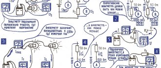
Very often the current or voltage in a circuit is much higher than the permissible value that a measuring device (voltmeter, ammeter or other) can measure.
In such cases, such parameters can be measured by adding special additional elements to the electrical circuit. The article will give a detailed explanation of what additional resistance is and why it is needed. A description and purpose of shunt devices will also be given, as well as the formulas used to calculate the parameters of such elements.
How is the shunt connected to the Ammeter?
The shunt is connected in parallel to the ammeter to expand the scale of the device. When a shunt is connected, part of the current flows past the device through the shunt and thereby reduces the load on the device.
Interesting materials:
Which team did Demis Karibidis play for? Which monitor is better for IPS or TN gaming? What laptop do you need to play this? What kind of dog plays the dog in the movie? What is the maximum level in the game Hay Day? Which side to play ping pong? What is the best game accelerator for Android? What genre is the GTA game? What award did the winner receive at the Olympic Games? What role does the white matter of the spinal cord play?
Resistance
Additional resistances are voltage-to-current measuring converters that consist of 1 or more load elements. Additional resistance for a voltmeter is necessary when measuring voltages that exceed the maximum permissible measurement limit of a given measuring device. These elements are no different in functionality from ordinary resistors. When making measurements in high-voltage electrical circuits, both the addition and the device itself must be connected in series to the electrical circuit.
With a series connection, we find the amperage using the following formula:
Where:
- I is the measured current.
- U is the voltage of the electrical circuit.
- Ri is the resistance of the voltmeter.
- Rd - additional resistive resistance.
When it is necessary to increase the nominal operating mode of the device several times, this can be done using this simple calculation:
The formula for calculating the additional resistance itself is as follows:
Thanks to this expression, it can be determined that the value of the additional load will always be “n–1” greater than the measured value itself.
The above calculation of additional resistance allows us to significantly increase the nominal measurement limit, making them both direct and alternating voltages. For AC electrical circuits, resistive elements based on bifilar materials are used. Windings made of such materials are used to eliminate the influence of the reactive component.
Direct current measurements are made with the addition of manganin resistors. Their windings meet the basic requirement, which is that as the load increases, the resistor will not heat up and thereby reduce the load itself.
Connecting fire extinguishing modules to Signal-20M.
The load connection in the new Signal-20M is better designed, but this device can only be used in fire extinguishing systems with finely sprayed water TRV.
There is, of course, an interesting possibility, described in the article Fire extinguishing based on S2000M and S2000-KDL.
Launching the outputs of the Signal-20M device is no different from launching the outputs of the S2000-SP2 ISP2 addressable devices and the S2000-KPB interface devices under the control of the S2000M (not to be confused with connecting the S2000-KPB as a slave to the S2000 -ASPT").
But this is a slippery slope and I consider it here as an example.
The new Signal-20M device has as many as 4 outputs that allow you to connect fire extinguishing modules.
Connection diagram for the actuator of the AUP launch circuit:
Quote from the instruction manual:
The circuit allows you to connect one actuator of the AUP launch circuit to the output of the device: a squib, a locking device or another device that has low resistance (units... tens of Ohms). Elements for monitoring the health of the line (4.7 kOhm resistor and diode type 1N5400 or similar) should be placed in the housing of the actuator or in the mounting compartment of the device. The circuit provides monitoring of the health of the device and communication line both in the on and off state. In the off state, the presence of a terminal element (4.7 kOhm resistor) is monitored using a small current of reverse polarity. In the on state, the health of the communication line and the actuator is monitored by monitoring the current consumption of the output circuit (straight polarity).
No additional resistance is provided.
Symbols on diagrams
On diagrams in Europe and the CIS it is indicated by a rectangle and a Latin letter R. According to GOST, on domestic diagrams the resistance rating is not indicated, but only the part number (R). However, if there is a number below the part image, such as 120, it will default to read 120 ohms.
The table contains examples of part designations.
| Basic designation |
| 0.125 W |
| 0.25 W |
| 0.5 W |
| 1 W |
| 2 W |
| 5 W |
| Variable |
| Trimmer |
What is the purpose of shunts and additional resistors
The frame of the magnetoelectric device has a coil made of thin wire designed for a very small current. Therefore, magnetoelectric ammeters can measure currents of several tens of milliamps.
What to do if you need to measure a much larger current, for example, several tens of amperes? Maybe rewind the device winding with a thicker wire? No, such a decision will be unsuccessful. The frame of the device will become very heavy, friction in the supports and the error of the device will increase. In addition, you will have to install spiral springs made of thicker wire. They will have greater rigidity, and the forces of electromagnetic interaction will not be able to turn the arrow of the device.
Symptoms of a problem
Malfunctions of the interior heating fan will be especially noticeable in the winter season. Failure of this system can be manifested by a complete lack of rotation of the electric motor, constant operation of the motor at maximum speed, or periodic turning on of the device. Regardless of the cause of the malfunction, replacing the Niva Chevrolet heater fan or repairing it can be done with your own hands.
Heater and cooling fan repair
If the motor winding is burned out, then only experienced craftsmen can do the rewinding themselves at home. If the motor completely fails, you will need to purchase an original product or its equivalent.
Replacement of the electric motor is carried out on your own or at a service station. If repairing the electrical system of a car is being done for the first time, you should strictly follow the step-by-step instructions, and also carefully monitor the correct connection of the wires.
Attention! It is not recommended to use used engines for replacement, because it is quite difficult to accurately assess their condition.
Additional current-limiting resistor in the starting circuit S2000-ASPT
Is it necessary or not to install an additional resistor in the starting circuit of the fire extinguishing modules? The question is interesting, but the answer is not easy to find.
An experiment carried out by chance to launch fire extinguishing modules from one fire extinguishing unit Rubezh MPT-1 R3 showed that the current at the moment of start-up increases until the emergency cutoff of the starting output.
This is also why connecting several fire extinguishing modules to one output is a big question.
And incorrect connection of the unused output PUSK S2000-ASPT leads to a short circuit through the winding of the input transformer.
Here is an incorrect diagram in which, at the moment of starting, a short circuit occurs through a section of cable after the load connection module (LCM):
Moreover, the S2000-ASPT device does not monitor that at the moment of start-up a short circuit occurs and burns out.
These cases indicate that the issue of using additional resistors included in the starting circuit to limit the current remains relevant.
What prompted me to write this article was this diagram of connecting powder fire extinguishing modules in a project that was put into operation:
What the experts say.
A whole discussion arose, which began with a message in the Pozharka chat - a club of professional participants in the fire protection industry:
Good afternoon Tell me, do all engineers install a limiting resistor on the ASPT to start extinguishing? And how do you calculate the resistor value?
Colleagues will burst into conversation. So explain, dear engineers. Nobody installs limiting resistors? And do you think that 12 amps at the output is normal? Why then calculate these resistors in tech. documentation?
What does the S2000-ASPT and S2000-KPB instruction manual say?
The S2000-ASPT operating manual does not say anything about additional resistances in the starting circuit; it contains the following :
The AUP launch control circuit is connected to the “P” terminals. The output parameters for connecting the AUP launch control circuit are given in Table 2.1. If the electric starting element of the AUP requires additional current limitation, then a limiting resistor must be connected in series with it. The calculated value of the limiting resistor Rolim is determined by the formula: Iav required operation current, [A] Rwire – resistance of the wires between the S2000-ASPT unit and the AUP, [Ohm]; RAUP – average equivalent resistance of the squib (incandescent bridge), [Ohm]. Finally, the value of the current-limiting resistor is selected by the nearest lower value from the E24 series. The calculated value of the allocated power Wlim is determined by the formula:
Nothing is said about the case when all fire extinguishing modules are connected to the S2000-KPB slave (connected to the S2000-ASPT via RS485-2) and connection to the S2000-ASPT starting circuit is not required.
DURING COMMISSIONING WORK, AND ALSO IF ANY OF THE OUTPUTS IS NOT USED, A RESISTOR MUST BE CONNECTED TO ITS TERMINALS: 1.0 kOhm - 1 W.
But it is necessary to somehow roughen the starting circuit so that the device does not go into fault mode.
How to connect fire extinguishing modules in the Bolide fire extinguishing system?
I think that it is best to always use a slave “S2000-KPB” (this is not difficult, since one starting device is rarely used) and connect fire extinguishing modules to the outputs of the “S2000-KPB” without current-limiting resistors, since the “S2000-KPB” protects its outputs.
In order to distribute in time the moments when fire extinguishing modules are activated, when setting up in pprog, it is necessary to specify the offset time between output launches and the duration of the trigger pulse. For example, 7 sec and 4 sec. Then the fire extinguishing modules will be launched one by one. This will allow the power channel to be used only to launch one fire extinguishing module at any given time.
For greater reliability, when using several S2000-KPBs, you can distribute power among them using a special safe power switching device.
Source
Properties in theory and practice
The main property of this radio component is resistance. Measured in ohms (ohms).
Let us first examine the concept of active resistance. It is so called because all materials have it (even superconductors, even if it is 0.00001 Ohm). And it is this that is fundamental for resistors.
What the theory says
In theory, a resistor has a constant resistance, which does not depend on external conditions (temperature, pressure, voltage, etc.).
The graph of current versus voltage is straightforward.
Under ideal and mathematical conditions, a resistor has only active resistance. There are nonlinear and linear resistors by type.
What really
In fact, all resistors have a non-linear dependence of current on voltage. That is, its resistance also depends on external conditions, specifically on temperature.
Of course, this dependence is not the same as for semiconductors, but it exists. And most importantly, this radio component has capacitance and inductance. In addition to active resistance, there is also reactive resistance.
Reactance differs from active resistance in that it passes electric current differently at different frequencies.
For example, for direct current the resistance is 200 Ohms, and if there are high inductance values, then at frequencies above 2 kHz, the resistance will already be 250 Ohms.
This is why resistors are made from different materials. They come in ceramic, carbon, wire and have different tolerances and errors. An SMD part has lower capacitance and inductance than a DIP part.
There are also special types of resistors with a more pronounced nonlinear current-voltage characteristic. If for ordinary resistors the current-voltage graph is slightly non-linear, then for this type of part it is avalanche-like.
