Inductance and its calculation:
The basic relationship for the magnetic field is the principle of magnetic flux continuity:
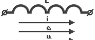
In Fig. 1.12, a and b illustrate the difference between flow and flux linkage, and the number of lines on a conventional scale is equal to the magnitude of the flow.
Induction is measured in teslas (tl), magnetic flux and flux linkage are measured in webers (wb). Inductance of a solitary circuit, equal to the ratio of flux linkage to current:
is proportional to the magnetic permeability of the medium in which it is located and is determined by the configuration of the circuit. The unit of inductance is henry (hn). To calculate the inductance of a circuit, it is necessary to first calculate its magnetic field according to the basic relationship - the law of total current:
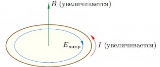
establishing a connection between the magnetic field strength and the total current I - the algebraic sum of currents coupled with the path of integration. In this case, the positive direction of the current I is related to the direction dI of the bypass by the rule of the right screw. Magnetic field strength is measured in a/m, magnetic permeability in Hz/m. If the flux linkage of the circuit changes over time, then e appears in the circuit. d.s. induction e, the magnitude and direction of which is determined by the law of electromagnetic induction:
where E is the intensity vector of the electric field induced in the circuit. Thus, the law of electromagnetic induction relates the change in the magnetic field with the resulting electric field. Maxwell postulated a generalization of this law, which consists in the fact that an electric field arises when a magnetic field changes in any medium, and not just in a conducting circuit.
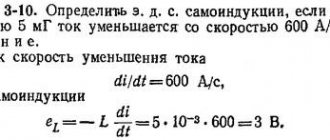
The law of electromagnetic induction, discovered by Faraday in 1831, was supplemented by Lenz in 1832-1834. They established a general rule: h. d.s. Induction always strives to create a current directed so as to prevent a change in the flux adhering to the circuit. When the current in the circuit changes, the flux linkage ψL created by this current changes, and e is induced in the circuit. d.s. self-induction
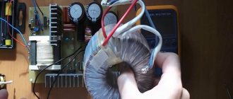
Toroid and Solenoid Inductance
If a winding is applied to a ring core—a toroid made of a material with permeability µ > µ0—not along its entire length (Fig. 1.13), then only part of the flux passes through the core, the rest—the leakage flux—is closed in the air. The toroid, which contains turns densely and evenly distributed along the entire length of the core (Fig. 1.14), is remarkable in that almost the entire magnetic flux is concentrated in the core, i.e., there is no leakage flux. The field strength vector lines are circles interlocking with all turns. Due to symmetry, the field strength at each point of the circle is constant in magnitude; in direction it coincides with the tangent to the circle.
Toroids are widely used in transformers, magnetic amplifiers and electrical measuring instruments.
Let the toroid have a rectangular cross-section with a height H, with radii r1 and r2, and the magnetic permeability of the material µ.
According to the law of total current for a circle with radius
where
that is, the field strength decreases as it approaches the outer edge of the toroid. This applies equally to induction
Flux in the toroid core
and flux linkage
Hence the inductance of the toroid
If the calculation is carried out for the center line I and the field in the toroid is approximately assumed to be uniformly distributed, then the intensity
where w0 is the number of turns per unit length, and the magnetic flux and inductance, respectively,
Typically, in real toroids, the ratio that leads with these approximate formulas to an error not exceeding 1.2%. The last formula for inductance can also be applied to a long solenoid, considered as part of a toroid of infinitely large radius. For a solenoid of finite length µ=µ0
where k
As an accurate calculation shows, this coefficient depends on the ratio of the diameter D of the coil to its length I (Fig. 1.15). At = 0.1 the coefficient k is 0.96, therefore at
Factors and SI prefixes for the formation of decimal multiples and submultiples and their names
| Multiple SI prefixes | SI prefixes |
| Deca-(101). | Deci- (10−1). |
| Hecto- (102). | Centi- (10−2). |
| Kilo- (103). | Milli- (10−3). |
| Mega (106). | Micro (10−6). |
| Giga- (109). | Nano- (10−9). |
| Tera- (1012). | Pico- (10−12). |
| Peta- (1015). | Femto- (10−15). |
| Exa- (1018). | Atto- (10−18). |
| Zetta- (1021). | Zepto- (10−21). |
| Iotta- (1024). | Iocto- (10−24). |
Two-wire line inductance
A two-wire line (Fig. 1.16, a) consists of two parallel wires of the same radius r0, having a greater length I compared to the distance d between them. Magnetic permeability of the wire material (g, environment) is µ0. The currents I in the forward and return wires differ only in direction; the origin of coordinates is taken at the center of the cross section of the left wire.
For an individual wire, due to its axial symmetry, neglecting the field distortion at its ends, applying the total current law to a circle of radius gives:
When integrating over a circle lying inside a separate wire, only part LX of the total current flowing inside a circle of radius x is covered, equal to when the current is uniformly distributed over the cross section
In the air between the wires on the line connecting the centers of their sections, the directions of the fields created by both currents according to the right screw rule coincide and the field strengths and induction add up:
The same formulas are also valid for i.e. outside the line, but here they give the field difference.
Inside the left wire of the line, the field strength and induction from both wires will be:
Inside the right wire, respectively,
In Fig. Figure 1.16b shows the distribution of field strength and induction along the x axis for the magnetic permeability of the wire material µ > µ0. In the middle between the wires the field is minimal, but does not go to zero. The field is also not zero on the wire axes.
On the inside of the wires, the field strength and induction are greater than on the outside. Unlike field strength, induction has a discontinuity at the surface of the wires. To calculate the line inductance, it is necessary to find the flux linkage. The elementary flux passing through the Idx pad in the air between the wires is
All flow between wires is external flow
at the same time it is an external flux linkage, since it couples with the circuit once. That's why
and the corresponding external inductance
For most lines, the distance d between the wires significantly exceeds the radius r0 of the wires. In this case
To determine the internal inductance corresponding to the internal flux, for d > r0, the field inside the line wire can be calculated as the field of an isolated wire, since the field created by the second wire inside the first, compared to the field of the first, is negligible. Then the elementary flux inside the wire
Since the flow dФi does not cover the entire current, but only part of it [see. formula (1.3)], elementary flux linkage
All flow between wires is external flow
Accordingly, the internal inductance
Total line inductance
With copper or aluminum wires () in most cases the second term can be neglected compared to the first and then
For steel wires (), the main part of the flux is internal flux and inductance
will practically not depend on the distance between the wires.
Hydraulic model
The operation of an inductor can be compared to the operation of a hydraulic turbine in a flow of water. The flow of water directed through a turbine that has not yet been spun up will feel resistance until the turbine is completely spun up.
Next, the turbine, which has a certain degree of inertia, rotates in a uniform flow, practically without affecting the speed of water flow. If this flow is suddenly stopped, the turbine will still rotate by inertia, creating water movement. And the higher the inertia of a given turbine, the more it will resist changes in flow.
Soldering iron YIHUA 8858
Updated version, power: 600 W, air flow: 240 l/h...
More details
Also, an inductive coil resists changes in the electric current flowing through it.
Mutual inductance and its calculation
For two circuits having w1 and w2 turns with currents I1 and I2 (Fig. 1.17), the flux of the first circuit, determined by the current of this circuit, the self-induction flux Ф1l, can be decomposed into the leakage flux Ф1s, penetrating only this circuit, and the mutual induction flux Ф1m, also penetrating the second circuit:
The flux linkage corresponding to flow F11 (provided that this flow penetrates all turns of the primary circuit is equal to
and leakage flux linkage
Similarly for the second circuit
The flux linkage of the second circuit, determined by the current of the first,
and the flux linkage of the first circuit, determined by the current of the second,
It can be shown that
The value M is called mutual inductance and is determined by the configuration of the circuits, their relative position and the magnetic permeability of the medium. Mutual inductance is also measured in henry (H). The total flow passing through the first circuit is
Total primary circuit flux linkage
and accordingly for the second circuit
In these algebraic sums, the first term is always positive, and the sign before the second term is determined by the direction of the currents in the circuits; a positive sign corresponds to the case when the directions of flows Ф1м and Ф2м coincide (see Fig. 1.17). From the above it is clear that
Thus, mutual inductance and inductances always satisfy the inequality
and the coupling coefficient of two circuits used in technical calculations
Similarly, in a system of many loops, the flux linkage of the loop is determined by the currents of all loops:
where Lq is the inductance of the qth circuit, Mqp = Мрq is the mutual inductance of the qth and pth circuits. The general technique for calculating the mutual inductance of circuits is to find the flux linkage that penetrates the circuit q, but created by the current of the pth circuit, and divide it by this current.
General information
In order to understand what the inductance of the coil depends on, it is necessary to study in detail all the information about this physical quantity. The first step is to consider the accepted international designation of the parameter, its purpose, characteristics and units of measurement.
The first letter of the surname of another famous physicist, Emilia Lenza, was taken as a designation for inductance in formulas and when carrying out calculations. Today, the symbol L continues to be used when referring to this parameter.
The outstanding American physicist Joseph Henry was the first to discover the phenomenon of inductance. In his honor, physicists named the unit of measurement in the international SI, which is most often used in calculations. In other systems (Gaussian and SGS), inductance is measured in centimeters. To simplify the calculations, a relationship was adopted in which 1 cm equals 1 nanohenry. The very rarely used SGSE system leaves the self-induction coefficient without any units of measurement or uses the stathenry value. It depends on several parameters and is approximately equal to 89875520000 henry.
Among the main properties of inductance are:
- The parameter value can never be less than zero.
- The indicator depends only on the magnetic properties of the coil core, as well as on the geometric dimensions of the circuit.
Mutual inductance of two parallel two-wire lines
Let two parallel two-wire lines be arranged symmetrically as shown in Fig. 1.4. Under the condition d> r0, the internal flux in the wires can be neglected compared to the external one. The magnetic flux passing through the first line and created by the current I2 of the second can be found as the sum of the fluxes created by each of the wires of the second line separately. Then the magnetic flux penetrating the first line
distances from the wire of line 1 to the wires of line 2.
Magnetic flux Ф is at the same time the flux linkage of the first line, since it couples with it once; That's why
and mutual inductance
To reduce the coupling coefficient between communication lines l and transmission 2, a transposition of the communication line is used, which consists in crossing the wires of the communication line at equal distances; then the total flux linkage will be zero.
Inductive reactance - how to find it
A real coil has not only reactive, but also ordinary resistance. Inductive reactance is determined by the formula:
XL=2*P*v*L
The following notations are used here:
- XL is the value under consideration.
- The symbol “P” represents the number Pi.
- V represents frequency.
- L is a designation for the amount of inductance.
It should be noted that the value (2*P*v) represents a circular frequency, which is denoted by the Greek symbol “omega”.
Coils with different cores
The quantity under consideration obeys Ohm's law. The formula looks like this:
I=U/XL
I, U represent current and voltage, XL is inductive reactance.
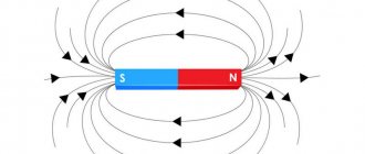
Coil magnetic field configuration
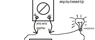
To determine the required value, you can use the given formulas. You can use an ammeter and a voltmeter. The first of them must be connected in series, the second in parallel.
The following must be taken into account. In fact, in a circuit in which inductance is connected, there are two types of resistance: active and reactive. By measuring current and voltage, you can determine their resulting value. It must be remembered that it is not their simple sum.
The fact is that in an alternating circuit, where there is only a coil and no capacitor, the voltage is ahead of the current by a quarter of the oscillation period. This value is equal to 90 degrees.
The impedance is determined as follows. To do this, you need to draw a corresponding diagram. If you plot the normal value horizontally, and the reactive value vertically, and then build a rectangle using these vectors, then the length of its diagonal will be equal to the full value.
Magnetic field of a wire
For example, if you select the elements of the circuit in such a way that both of these values are equal in absolute value, then the required part will be determined as their total value multiplied by the square root of two.
In order to obtain information about the dependence of inductive reactance on frequency, you can use an oscilloscope.
When using alternating current, it is necessary to take into account not only ordinary, but also inductive reactance. It occurs if there is a coil in the electrical circuit.
Linear and nonlinear inductors
For linear materials, the magnetic permeability µ does not depend on the field strength and the characteristic for them is depicted by a straight line (Fig. 1.18, a). Magnetic permeability is proportional to the tangent of the angle a of the slope of this straight line:
where k is the scale factor.
Nonlinear materials include ferromagnets and iron, nickel, cobalt and gadolinium. The first three elements are important in electrical engineering, mainly in the form of alloys. In nonlinear materials, the magnetic permeability is very high and depends on the field strength.
Similar to nonlinear dielectrics, the static magnetic permeability can be determined from the initial magnetization curve B (H) (Fig. 1.18, b)
and differential, and with rapid field changes - dynamic magnetic permeability
In Fig. 1.18, b these permeabilities are presented as a function of field strength. The maximum values of magnetic permeability in very pure iron and in some alloys, for example in permalloy (an alloy of iron and nickel with various additives), are hundreds of thousands of times higher than the magnetic constant equal to
magnetic permeability of vacuum.
In alternating magnetic fields in ferromagnets, the phenomenon of magnetic hysteresis occurs (Fig. 1.19), which consists in the discrepancy between the B (H) curve as the field strength increases and the curve as the field decreases.
The curve connecting the tops of the hysteresis loops is called the main magnetization curve and practically coincides with the initial magnetization curve. Ferromagnetic properties depend on temperature and appear only in a certain temperature range.
To calculate the inductance, the main one is the dependence of the flux linkage ψ on the current I, called the Weber-ampere characteristic.
Depending on the core material, the toroids will also be linear or nonlinear in terms of their weberampere characteristics. A nonlinear toroid is considered as an example.
For a toroid, the webampere characteristics ψ (I) on the appropriate scale coincide with curves B (H); therefore the straight line and curves in Fig. 1.18 a and b also correspond to weberampere characteristics at the values indicated in parentheses.
For nonlinear toroids, the concepts of static inductance are introduced
and differential as well as dynamic inductance
which are functions of current (see Fig. 1.18, b); for linear toroids these inductances are the same.
Similar to inductances in nonlinear circuit systems, static mutual inductance is introduced
and differential, mutual inductance, as well as dynamic
Historical reference
The symbol L used to denote inductance was adopted in honor of Heinrich Friedrich Emil Lenz, who is known for his contributions to the study of electromagnetism, and who derived Lenz's rule on the properties of induced current. The unit of inductance is named after Joseph Henry, who discovered self-inductance. The term inductance itself was coined by Oliver Heaviside in February 1886.
Among the scientists who took part in the study of the properties of inductance and the development of its various applications, it is necessary to mention Sir Henry Cavendish, who conducted experiments with electricity; Michael Faraday, who discovered electromagnetic induction; Nikola Tesla, who is famous for his work on electrical transmission systems; André-Marie Ampere, who is considered the discoverer of the theory of electromagnetism; Gustav Robert Kirchhoff, who studied electrical circuits; James Clark Maxwell, who studied electromagnetic fields and their particular examples: electricity, magnetism and optics; Henry Rudolf Hertz, who proved that electromagnetic waves do exist; Albert Abraham Michelson and Robert Andrews Millikan. Of course, all these scientists studied other problems that are not mentioned here.
Oscillatory circuit
A capacitance and an inductive element connected in a circuit form an oscillatory circuit with pronounced frequency properties and will be a resonant system. The system uses a capacitor, changing the capacitance of which, you can correct the frequency properties.
If you measure the resonant frequency using a known capacitor, you can determine the inductance of the coil.
Inductance is an important element in various fields of electrical engineering. For proper use, you need to know all the parameters of the elements used.
A device that allows you to determine the parameters of inductors, including quality factor, may be called an L-meter or Q-meter.
Sensors
What does the resistance of a conductor depend on?
Changing the voltage across the inductor is used to control environmental parameters. Such sensors are sensitive to the approach of products with ferromagnetic properties. They are used for contactless fixation of the position of individual parts of mechanisms, gate leaves and other products.
When properly designed, they can withstand adverse external influences well. Potential consumers are attracted by simplicity, reasonable cost, and durability. It is easy to make a functional sensor with your own hands if necessary. Such devices can be easily combined with other components of automation systems.