Definition, formula, how current is measured.
Electric current strength (I) is a physical quantity numerically equal to the charge q passed through the cross section of the conductor per unit time t. The SI unit of current is Ampere (A).
Current strength in practice is often expressed in kiloamperes (kA), milliamperes (mA), microamperes (µA):
- 1 kA = 1000 A = 1 103 A;
- 1 mA = 0.001 A = 1 10-3 A;
- 1 µA = 0.000001 A = 1 10-6 A.
The unit of measurement of electric current is named after the French mathematician and physicist André-Marie Ampère (1775-1836).
Interesting fact! As is known, electrons can move in conductors. So, we can say that a current of 1 A flows through the cross-section of a conductor if 6.242⋅1018 electrons pass through it in 1 second.
Electricity
Electric current flows through the wires. Moreover, it “flows”, almost like water. Let's imagine that you are a happy farmer who decided to water his garden with a hose. You opened the tap slightly, and water immediately ran through the hose. Slowly, but still she ran.
The jet force is very weak. Then you decided that more pressure was needed and opened the tap to its fullest. As a result, the stream will flow with such force that not a single tomato will be left unattended, although in both cases the diameter of the hose is the same.
Now imagine that you are filling two buckets from two hoses. One of them has stronger pressure, the other weaker. The bucket into which water is poured from a hose with strong pressure will fill faster. The thing is that the volume of water for an equal period of time from two different hoses is also different. In other words, a much larger number of water molecules will run out of the green hose than from the yellow hose in the same period of time.
If we take a conductor with current, the same thing will happen: charged particles will move along the conductor, just like water molecules. If more charged particles move along the conductor, the “pressure” will also increase.
- Electric current is the directed movement of charged particles.
Movement of charge along a conductor
As you already know, electric current is the ordered movement of charged particles. We say that particles are “charged” - this means that they have a certain charge $q$.
Accordingly, when such particles move, a certain charge is transferred. Each free electron in a metal carries a charge. Each ion in a solution of acids, salts or alkalis also carries a charge.
It is logical that the more particles move from one section of the chain to another, the greater the total charge they will transfer.
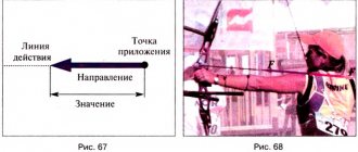
What determines the intensity of the action of electric current? It has been experimentally proven that the intensity (degree of action) of the electric current depends precisely on the magnitude of this transferred charge .
Current strength
There immediately arises a need for a quantity with which we will measure the “pressure” of the electric current. Such that it depends on the number of particles that flow through the conductor.
Current strength is a physical quantity that shows how much charge has passed through a conductor.
How is the current indicated?
The current strength is indicated by the letter I
| Current strength I = q/t I - current strength [A] q - charge [C] t — time [s] |
Current strength is measured in Amperes. The unit of measurement was chosen for a reason.
Firstly, it is named after the physicist André-Marie Ampère, who studied electrical phenomena. And secondly, the unit of this quantity was chosen based on the phenomenon of interaction of two conductors.
Here, unfortunately, it is impossible to draw an analogy with a water supply system. Hoses with water do not attract or repel each other close to each other (which is a pity, it would be funny).
When current flows through two parallel conductors in the same direction, the conductors attract each other. And when in the opposite direction (along the same conductors) they repel.
The unit of current 1 A is taken to be the current at which two parallel conductors 1 m long, located at a distance of 1 m from each other in a vacuum, interact with a force of 0.0000002 N.
Task
Find the current strength in the circuit if a charge equal to 300 mC passes through it in 2 seconds.
Solution:
Let's take the formula for current strength
I = q/t
Let's substitute the values
I = 300 mC / 2 s = 150 mA
Answer: the current in the circuit is 150 mA
Electrical voltage
It is easy to imagine that electric current is similar to the flow of water in a hose. If you hold both ends of the hose at the same level, there will be no water flow.
If one of the ends is lowered, then water will flow from a higher level to a lower one. The difference in water levels is similar to the voltage of the current source.
The higher the voltage (the greater the difference in water levels), the greater the current in the circuit (the faster the water moves in the hose). The work of the electric field that creates an electric current is called the work of the current Ael.
The work of current depends on voltage. Voltage shows how much work an electric field does when moving a unit electric charge from one point to another and is denoted by the letter U.
U=Ael/q
The unit of electrical voltage is called the volt.
1 V = 1 J/C
A device used to measure the voltage at the poles of a current source or at some section of the circuit is called a voltmeter. In appearance and design, a voltmeter is very similar to an ammeter.
On electrical diagrams, a voltmeter is depicted as a circle with the letter V.
Current formula
The formula for dummies will look like this:
Where
I - actual current strength, Amperes
N - number of electrons
t is the period of time during which these electrons travel through the cross section of the conductor, seconds
The more correct (official) formula looks like this:
Where
Δq is the charge over a certain period of time, Coulomb
Δt — the same period of time, seconds
I - current, Amperes
What's so funny about these two formulas? The thing is that an electron has a charge of approximately 1.6 10-19 Coulomb. Therefore, for the current strength in the wire (conductor) to be 1 Ampere, we need a charge of 1 Coulomb = 6.24151⋅1018 electrons to pass through the cross section. 1 Coulomb = 1 Ampere · 1 second.
So, now we can officially say that if 6.24151⋅1018 electrons fly through the cross-section of a conductor in 1 second, then the current strength in such a conductor will be equal to 1 Ampere! All! There is no need to invent anything else! Tell your physics teacher so.)
If the teacher doesn’t like your answer, then say something like this:
Current strength is a physical quantity equal to the ratio of the amount of charge passing through the surface (read as through the cross-sectional area) over some time. Measured as Coulomb/second. To save time and according to other moral and aesthetic standards, they agreed to call the coulomb/second Ampere, in honor of the French physicist.
Electrical resistance
If you include different conductors in a circuit, the current strength will be different.
Let's look at the dependence of the current on the type of conductor connected to the circuit. Let's assemble a circuit consisting of a current source, a key, a light bulb and an ammeter. We will connect conductors in series of the same size, but made of different materials: iron, copper, nickel.
The glow of the light bulb and the current strength are greater when connecting an iron conductor than when connecting a nickel conductor, but less than when connecting a copper one.
Different conductors have different resistance to electric current due to the peculiarities in the structure of their crystal lattice.
This dependence remains valid not only for metals, but also for conductors of a different nature, for example electrolytes. Electrical resistance is a physical quantity characterizing the ability of a conductor to prevent the flow of electric current in this conductor.
Resistance is designated by the letter R.
The unit of resistance is called Ohm (1 Ohm). 1 Ohm is the resistance of a conductor in which, at a voltage at the ends of 1V, the current strength is 1A:
1 Ohm = 1V/1A
Current strength and resistance
Let's take another look at the water hose and ask ourselves questions. What does water flow depend on? The first thing that comes to mind is pressure. Why do the water molecules move from left to right in the picture below? Because the pressure on the left is greater than on the right. The greater the pressure, the faster the water will flow through the hose - this is elementary.
Now the question is: how can we increase the number of electrons across the cross-sectional area?
The first thing that comes to mind is to increase the pressure. In this case, the speed of water flow will increase, but you won’t increase it much, since the hose will break like a hot water bottle in Tuzik’s mouth.
The second is to install a hose with a larger diameter. In this case, we will have more water molecules passing through the cross section than in a thin hose:
All the same conclusions can be applied to an ordinary wire. The larger its diameter, the more current it can “pull” through itself. The smaller the diameter, it is advisable to load it less, otherwise it will “tear”, that is, it will burn out stupidly. This is the principle behind fuses. There is a thin wire inside such a fuse. Its thickness depends on the current strength it is designed for.
fuse
As soon as the current through the thin fuse wire exceeds the current for which the fuse is designed, the fuse wire burns out and opens the circuit. Current can no longer flow through a blown fuse, since the wiring in the fuse is broken.
burnt fuse
Therefore, power cables, through which hundreds and thousands of amperes “run,” are taken with a large diameter and try to be made of copper, since its resistivity is very low.
How to measure current?
In order to measure the value of current, we must use special devices - ammeters. Currently, current can be measured using a digital multimeter, which can measure current, voltage, resistance and much more. In order to measure the current, we must insert our device into the open circuit like this.
You can read more details on how to do this in this article.
I also advise you to watch a training video where a very smart teacher explains in simple language what “current strength” is.
Basic units of current
The basic unit of current measurement is the ampere (short symbol: A). Ampere, named after the physicist Henri Ampere, is included in the International System of Units (SI).
If 1 coulomb of electricity passes through a cross section within 1 second, then the current in that conductor is equal to one ampere. How auxiliary units are used:
- milliamps (ma), one thousandth or 10-3 amperes;
- microamps (µA), one millionth or 10-6 amperes.
Current strength is an important parameter, knowledge of which will help in choosing cables with the optimal cross-sectional size for the planned load.
Current strength - designation and basic formulas
In formulas when calculating such a parameter as current strength, the designation of its value using the letter “I” is generally accepted. The basic formula looks like I=q/t, where q is the amount of electricity, and t is the time period.
You can also use parameters such as:
- actual voltage (U);
- power (P).
In this case, the formula I= P/U is applied. Obtaining current strength by calculation is relevant in cases where the use of measuring instruments is impossible, for example, at the stage of designing electrical networks.
Exercises
Exercise No. 1
Express in amperes the current equal to $2000 \space mA$;
$100 \space mA$; $55 \space mA$; $3 \space ka$. Given: $I_1 = 2000 \space mA$ $I_2 = 100 \space mA$ $I_3 = 55 \space mA$ $I_4 = 3 \space kA$
Show solution and answer
Hide
Solution:
$I_1 = 2000 \space mA = 2000 \cdot 10^{-3} \space A = 2 \space A$.
$I_2 = 100 \space mA = 100 \cdot 10^{-3} \space A = 0.1 \space A$.
$I_3 = 55 \space mA = 55 \cdot 10^{-3} \space A = 0.055 \space A$.
$I_4 = 3 \space kA = 3 \cdot 10^3 \space A = 3000 \space A$.
Answer: $I_1 = 2 \space A$, $I_2 = 0.1 \space A$, $I_3 = 0.55 \space A$, $I_4 = 3000 \space A$.
Exercise No. 2
The current strength in the electric stove circuit is $1.4 \space A$.
What electric charge passes through the cross section of its spiral in $10 \space min$? Given: $t = 10 \space min$ $I = 1.4 \space A$
SI: $t = 600 \space s$
$q — ?$
Show solution and answer
Hide
Solution:
We use the formula: $q = It$. $q = 1.4 \space A \cdot 600 \space c = 840 \space Cl$.
Answer: $q = 840 \space Kl$.
Examples of typical currents
Current values can be read on information plates on electrical receivers or in the manuals for these devices. The table below shows typical values of electric currents for various electrical receivers.
| Consumer | Current strength |
| Electric thermometer | about 0.00001 mA |
| Headphones | 1 mA |
| Incandescent lamp 60 W | 0.26 A |
| Incandescent lamp 75 W | 0.33 A |
| Fridge | 0.8 A |
| Smartphone charger (fast charging) | 2 A |
| Personal Computer | 0.87 - 2.6 A |
| Microwave | 3.5 A |
| Vacuum cleaner | 4 - 9 A |
| Washing machine | 6 - 10 A |
| Electric melting furnace | 15000 A |
| Thunderstorm lightning | 10,000 - 100,000 A (average 36,000 A) |
Power of some electrical appliances
When equipping a modern apartment, it is often necessary to solve problems of coordinating loads in individual lines. It is necessary to properly install a circuit breaker to prevent emergency situations. They start by clarifying the wiring parameters. Next, the groups of connected household appliances are checked.
Typical power consumption (W):
- personal computer – 170-1,250;
- laptop – 40-280;
- LCD TV – 120-265;
- iron – 450-1850;
- air conditioning – 1,200 – 2,500.
Which machine is suitable is determined taking into account all significant factors. Particular attention is paid to loads with high values of the reactive component of power.
Instruments for measuring current strength
An instrument for measuring current strength is called an ammeter, in addition to the topic of how current is measured. It can be pointer, digital and electronic. It is actively used in electrical laboratories, automotive industry, exact science and construction. According to the operating principle, it can be electromagnetic, magnetoelectric, thermionic, ferrodynamic, electrodynamic and digital. Measures both alternating and direct current.
It works due to the interaction of a magnetic field with a moving coil or core, which is located in the housing. All types are very easy to use. All the user needs to do is carefully study the instructions and operating instructions. As a rule, to start measuring, you need to touch the conductor using probes and press the corresponding button. Afterwards, the value in amperes will be displayed on the screen. It is worth pointing out that a voltmeter, a multimeter and a measuring screwdriver also measure current strength.
Ammeter
Application
When studying electric current, many of its properties were discovered, which made it possible to find practical application in various areas of human activity, and even to create new areas that would have been impossible without the existence of electric current. After practical application was found for electric current, and for the reason that electric current can be obtained in various ways, a new concept arose in the industrial sphere - electric power.
Electric current is used as a carrier of signals of varying complexity and types in different areas (telephone, radio, control panel, door lock button, and so on).
In some cases, unwanted electrical currents appear, such as stray currents or short circuit currents.
Use of electric current as an energy carrier
- obtaining mechanical energy in all kinds of electric motors,
- obtaining thermal energy in heating devices, electric furnaces, during electric welding,
- obtaining light energy in lighting and signaling devices,
- excitation of electromagnetic oscillations of high frequency, ultrahigh frequency and radio waves,
- receiving sound,
- obtaining various substances by electrolysis, charging electric batteries. Here electromagnetic energy is converted into chemical energy,
- creating a magnetic field (in electromagnets).
Use of electric current in medicine
Electrophoresis
- diagnostics - the biocurrents of healthy and diseased organs are different, and it is possible to determine the disease, its causes and prescribe treatment. The branch of physiology that studies electrical phenomena in the body is called electrophysiology. Electroencephalography is a method for studying the functional state of the brain.
- Electrocardiography is a technique for recording and studying electric fields during heart activity.
- Electrogastrography is a method for studying the motor activity of the stomach.
- Electromyography is a method for studying bioelectric potentials arising in skeletal muscles.
What does current depend on?
Since the current force is a scalar quantity that has a positive and negative charge, it depends on the power of the charge, the concentration of particles concentrated in the charge, the speed of their movement and the area of the conductor. It is also worth pointing out that it depends on the resistance value with voltage, magnetic field strength, number of coil turns, rotor power, conductor diameter and generator set parameter.
Dependence of electric current on resistance and voltage
Main types of conductors
Unlike dielectrics, conductors contain free carriers of uncompensated charges, which, under the influence of a force, usually an electrical potential difference, move and create an electric current. The current-voltage characteristic (the dependence of current on voltage) is the most important characteristic of a conductor. For metal conductors and electrolytes, it has the simplest form: the current strength is directly proportional to the voltage (Ohm's law).
Metals - here the current carriers are conduction electrons, which are usually considered as an electron gas that clearly exhibits the quantum properties of a degenerate gas.
Plasma is an ionized gas. Electric charge is transferred by ions (positive and negative) and free electrons, which are formed under the influence of radiation (ultraviolet, x-ray and others) and (or) heating.
Electrolytes are liquid or solid substances and systems in which ions are present in any noticeable concentration, causing the passage of electric current. Ions are formed through the process of electrolytic dissociation. When heated, the resistance of electrolytes decreases due to an increase in the number of molecules decomposed into ions. As a result of the passage of current through the electrolyte, ions approach the electrodes and are neutralized, settling on them. Faraday's laws of electrolysis determine the mass of a substance released on the electrodes.
There is also an electric current of electrons in a vacuum, which is used in electron beam devices.
What are the types of electric current in everyday life?
The shape of the current signal depends on the operation of the voltage source and the resistance of the medium through which the signal passes. Most often in practice, a home craftsman has to deal with the following types:
- a constant signal generated from batteries or galvanic cells;
- sinusoidal, created by industrial generators with a frequency of 50 hertz;
- pulsating, formed by transformations of various power supplies;
- pulsed, penetrating into the household network due to lightning discharges into overhead power lines;
- arbitrary.
The most common type is sinusoidal or alternating current: it powers all our devices.
Many semiconductor household appliances operate in modern wiring powered by sinusoidal voltage. They have non-linear resistance and violate the harmonic shape.
These noises accumulate throughout the entire circuit from a specific consumer to the supply transformer, distorting the ideal sine wave in an arbitrary manner. As a result, both the shape and magnitude of the supply voltage changes.
Current strength in a metal conductor: how it is used in domestic conditions
The ability of the internal structure of metals to differently influence the conditions of movement of directed charges is used to implement specific tasks.
To transmit electrical energy over long distances, metal conductors of increased cross-section with high conductivity are used: copper or aluminum. The more expensive metals silver and gold work inside complex electronic circuits.
All kinds of designs of wires, cords and cables based on them are reliably used in home wiring.
Tungsten and nichrome, which have high resistance, are used for heating devices. It allows the conductor to be heated to high temperatures with the correct selection of applied power.
This principle is embodied in numerous designs of electric heaters - heating elements.
The increased current strength in a metal conductor with good conductivity but a thin cross-section makes it possible to create fuses used as current protection.
They work normally under optimal load conditions, but quickly burn out during voltage surges, short circuits or overloads.
For several decades, fuses massively served as the main protection for home wiring. They have now been replaced with circuit breakers. But inside all power supplies they continue to work reliably.
Ohm's law
It has been experimentally proven that no matter how many times the voltage in a section of a circuit increases, the current strength in this section increases by the same amount. That is, the current strength in a conductor is directly proportional to the voltage at the ends of this conductor.
The graph of current versus voltage will be a straight line passing through the origin. It is called the current-voltage characteristic of the circuit.
The dependence of current strength on resistance shows that the greater the resistance of the conductor, the less current strength at the same voltage between the ends of the conductor. Therefore, the current strength in a conductor is inversely proportional to the resistance of the conductor
For a section of a circuit, the value of I is calculated using the formula of the German physicist Georg Ohm, who discovered in 1926 the law of the relationship between current strength, voltage and conductor resistance:
I=U/R,
- U – voltage (or voltage drop, or potential difference), measured in volts – symbol V or V;
- R – conductor resistance, measured in ohms – symbol Ohm or W.
Or according to the formula I=UG, where the designation G is conductivity or electrical conductivity (the reciprocal of resistance is measured in siemens, designation is Cm or S).
The calculation for the complete circuit is carried out using the formula I=e/R+r, where:
- e – EMF or electromotive force in the circuit, measured in volts;
- R is the total resistance of all devices included in the circuit;
- r – internal resistance of the voltage source.
The strength of the current depends on the electrical voltage (or potential difference, or EMF). In cases where r<>R, we can assume that it is inversely proportional to either the circuit resistance or the source resistance.
Ohm's law for a complete circuit.
The value of I is associated with an indicator of the rate of conversion of electrical energy - power P (units of measurement are watts - symbol W or W). For a linear circuit in which Ohm's law is observed, P is calculated using the formula:
P=IU or P=I2R=U2/R.
The value of I is directly proportional to the power: I=P/U. Higher power devices produce higher current.
Current in semiconductors and its characteristics
The electrical properties of semiconductors strongly depend on external conditions: temperature, light irradiation. To increase their own conductivity, special impurities are added to the structure.
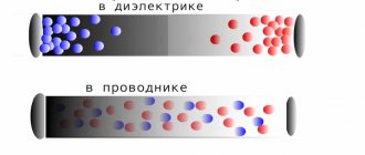
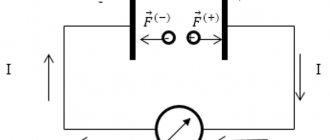
Therefore, inside the semiconductor, the current is created due to the intrinsic and impurity conductivity of the internal pn junction. The charge carriers of a semiconductor are electrons and holes. If the positive potential of the voltage source is applied to pole p, and the negative potential to pole n, then current will flow through the pn junction due to the movement they create.
When the polarity is applied in reverse, the pn junction remains closed. Therefore, in the picture above, in the first case, a light bulb is shown, and in the second, an extinguished one.
Similar pn junctions work in other semiconductor designs: transistors, zener diodes, thyristors...
All of them are designed to carry rated current. To do this, markings are applied directly to their body. Using it, they enter the tables of technical reference books and evaluate the semiconductor based on its electrical characteristics.
Example of calculating current strength for different connections
For example, let's take a circuit with parallel connection of two branches with identical resistors. The ammeter shows that the current strength in each branch is the same - 0.5 Ampere (A). The value of the current a little further from the junction of the branches will be equal to unity, i.e. are summed up:
0.5 + 0.5 = 1 A.
Let's measure the current in a series connection. At any point in the circuit, the ammeter will show the same value (0.5 A), regardless of the number of resistors and their resistance:
0.5 = 0.5 = 0.5 A.
Literature
- Aksenovich L. A. Physics in secondary school: Theory. Tasks. Tests: Textbook. allowance for institutions providing general education. environment, education / L. A. Aksenovich, N. N. Rakina, K. S. Farino; Ed. K. S. Farino. - Mn.: Adukatsiya i vyakhavanne, 2004. - P. 252-253, 259-260, 262-264, 267-269.
- Zhilko, V.V. Physics: textbook. allowance for 11th grade. general education institutions with Russian language training with a 12-year period of study (basic and advanced levels) /V. V. Zhilko, L. G. Markovich. — 2nd ed., revised. — Minsk: Nar. Asveta, 2008. - pp. 118-123, 132-141.
Series connection of resistors.
Let's start by looking at circuits whose elements are connected in series. And although we will only consider resistors as circuit elements in this article, the rules regarding voltages and currents for different connections will also be valid for other elements. So, the first circuit that we will disassemble looks like this:
Here we have a classic case of a series connection - two resistors connected in series. But let’s not get ahead of ourselves and calculate the total resistance of the circuit, but first consider all the voltages and currents. So, the first rule is that the currents flowing through all conductors in a series connection are equal to each other:
I = I_1 = I_2
And to determine the total voltage in a series connection, the voltages on the individual elements must be summed up:
U = U_1 + U_2
At the same time, according to Ohm’s law, the following relationships hold true for voltages, resistances and currents in a given circuit:
U_1 = I_1R_1 = IR_1U_2 = I_2R_2 = IR_2
Then the following expression can be used to calculate the total voltage:
U = U_1 + U_2 = IR_2 + IR_2 = I(R_1 + R_2)
But Ohm’s law is also valid for general voltage:
U = IR_0
Here R_0 is the total resistance of the circuit, which, based on two formulas for the total voltage, is equal to:
R_0 = R_1 + R_2
Thus, when resistors are connected in series, the total resistance of the circuit will be equal to the sum of the resistances of all conductors.
For example for the following circuit:
The total resistance will be equal to:
R_0 = R_1 + R_2 + R_3 + R_4 + R_5 + R_6 + R_7 + R_8 + R_9 + R_{10}
The number of elements does not matter, the rule by which we determine the total resistance will work in any case. And if in a series connection all resistances are equal (R_1 = R_2 = ... = R), then the total resistance of the circuit will be:
R_0 = nR
In this formula, n is equal to the number of elements in the chain. We've figured out the series connection of resistors, let's move on to parallel.
Current source efficiency
For closed circuit, power Pp
, allocated in the external section of the circuit, is called
useful power
.
It is equal to \(~P_p = I^2 \cdot R\) .
Taking into account Ohm's law for the circuit section \(~I = \dfrac{U}{R}\), the useful power can be found if any two of the three quantities are known: I
,
U
,
R
.
\(~P_p = U \cdot I\) , \(~P_p = I^2 \cdot R\) , \(~P_p = \dfrac{U^2}{R}\) .
For closed circuit, power Pt
, released at the internal resistance of the source, is called
lost power
.
It is equal to \(~P_t = I^2 \cdot r\) .
The total power
P
of the current source is equal to
\(~P = P_p + P_t = I^2 \cdot R + I^2 \cdot r = I^2 \cdot \left( R + r \right). \)
Efficiency of the current source
\(~\eta = \dfrac{P_p}{P}= \dfrac{I^2 \cdot R}{I^2 \cdot \left( R + r \right)} = \dfrac{R}{R + r}\).
Through charge and time
electricity is the amount of charge driven by the forces of an electric field that overcomes the conventional plane of a conductor, called the cross-section of the conductor, per unit time.
Definition of current strength
Thus, if the electric charge passed through a conductor in a certain time is known, then it is not difficult to find the value of this charge passed per unit time, that is: I = q/t
What is voltage and current?
By the way, what exactly are electric current and voltage? I think that no one really knows, because to know it you have to at least see it. Who can see the current running through the wires?
Yes, no one, humanity has not yet achieved such technologies to personally observe the movements of electric charges. All that we see in textbooks and scientific works is some kind of abstraction created as a result of numerous observations.
Well, okay, we can talk a lot about this... So let's try to figure out what electric current and voltage are. I will not write definitions; definitions do not give the very understanding of the essence. If interested, take any physics textbook.
Since we do not see the electric current and all the processes occurring in the conductor, then we will try to create an analogy.
And traditionally, the electric current flowing in a conductor is compared to water running through pipes. In our analogy, water is an electric current. Water runs through the pipes at a certain speed, the speed is the current strength, measured in amperes. Well, pipes are a conductor in themselves.
Okay, we imagined electric current, but what is voltage? Let's help now.
The water in the pipe, in the absence of any forces (gravity, pressure), will not flow; it will rest like any other liquid poured onto the floor. So this force, or more precisely, energy in our plumbing analogy, will be the same tension.
But what happens to the water running from a reservoir located high above the ground? Water rushes in a stormy stream from the reservoir to the surface of the earth, driven by gravitational forces. And the higher the reservoir is located from the ground, the faster the water flows out of the hose. Do you understand what I'm talking about?
The higher the tank, the greater the force (read voltage) acting on the water. And the greater the speed of the water flow (read current strength). Now it becomes clear and a colorful picture begins to form in my head.
Measurements
As shown above, some initial data can be obtained through practical measurements. The features of typical specialized devices are noted below.
Direct measurements
Wattmeters are produced in different modifications for ~220V and ~380V networks. Appropriate corrections are made during work operations. The probes should be connected taking into account the manufacturer's instructions and the appropriate location of the conductors.
As a rule, in device designs two coils are used with parallel and serial connection to the load. For increased accuracy, use professional instruments of the “laboratory” category.
Indirect measurements
These operations are performed using multimeters. Resistance, current and voltage are measured, after which the power is calculated.
Phase meters
These instruments measure the phase shift between several electrical parameters. With such a device, cos ϕ can be determined if the passport value is not in the accompanying documents for the equipment.
cos regulation
The negative impact of reactive components noted above is compensated for by special additions to the overall electrical circuit. Calculations are performed using the presented formulas.
What is EMF: explanation in simple words
EMF is understood as the specific work of external forces to move a unit charge in an electrical circuit. This concept in electricity involves many physical interpretations related to various areas of technical knowledge. In electrical engineering, this is the specific work of external forces that appears in inductive windings when an alternating field is induced in them. In chemistry, it means the potential difference that occurs during electrolysis, as well as during reactions accompanied by the separation of electrical charges.
In physics, it corresponds to the electromotive force created at the ends of an electrical thermocouple, for example. To explain the essence of EMF in simple words, you will need to consider each of the options for its interpretation. Before moving on to the main part of the article, we note that EMF and voltage are very similar concepts in meaning, but they are still somewhat different. In short, the EMF is on the power source without a load, and when a load is connected to it, it is already a voltage. Because the number of volts on the power supply under load is almost always slightly less than without it. This is due to the internal resistance of power sources such as transformers and galvanic cells.
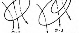
Electromotive force (emf), a physical quantity characterizing the action of third-party (non-potential) forces in direct or alternating current sources; in a closed conducting circuit is equal to the work of these forces to move a single positive charge along the circuit. If we denote the field strength of external forces by Etr, then the emf in a closed loop (L) is equal to , where dl is the element of the loop length. The potential forces of an electrostatic (or stationary) field cannot maintain a constant current in the circuit, since the work of these forces on a closed path is zero. The passage of current through the conductors is accompanied by the release of energy - heating of the conductors.
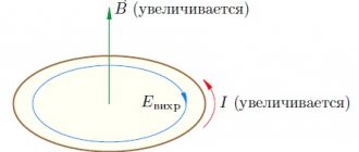
Third-party forces set in motion charged particles inside current sources: generators, galvanic cells, batteries, etc. The origin of third-party forces can be different. In generators, external forces are forces from the vortex electric field that arises when the magnetic field changes over time, or the Lorentz force acting from the magnetic field on electrons in a moving conductor; in galvanic cells and batteries - these are chemical forces, etc. Emf determines the current strength in the circuit at a given resistance (see Ohm's law). EMF, like voltage, is measured in volts.
What is EMF.
DC laws
Table of contents:
Electric current is the ordered movement of electric charges.
In metals, charge carriers are free electrons, in electrolytes - positive and negative ions, in semiconductors - electrons and holes, in gases - ions of both signs and electrons.
The direction of current in a conductor is taken to be the direction of positive charges. In the outer part of the circuit, which includes all its sections except the current source, the current flows from plus to minus, in the inner part, i.e. inside the current source, from minus to plus.
The section of the circuit inside the current source is called the internal part of the circuit, and the rest of the circuit, which includes current consumers, measuring instruments, control devices and connecting wires, is called the external part of the circuit.
The current strength I is the ratio of the charge q passing through the cross section of the conductor to the time of passage of this charge f:
Current strength is a scalar quantity. The SI unit of current is ampere (A). This is the SI base unit.
The current strength in a metal conductor is equal to the product of the concentration of free electrons n, the modulus of the elementary charge e, the speed of ordered movement of free electrons along the conductor v and the cross-sectional area of the conductor S:
The current strength in the circuit is measured using instruments - ammeters. The ammeter is connected to the circuit in series with the section in which the current is measured.
Current density j is the ratio of the current strength to the cross-sectional area of the conductor through which the current flows:
The current density is equal to the product of the concentration of free electrons, the modulus of the elementary charge and the speed of ordered movement of free electrons along the conductor:
Current density is a vector quantity. The current density vector is directed towards the ordered movement of positive charges along the conductor.
A conductor resists electric current. The resistance of the conductor R is equal to the ratio of the voltage U on the conductor to the current I in it:
Resistance is a scalar and always positive quantity. The SI unit of resistance is ohm.
The resistance of linear conductors is directly proportional to their length I and inversely proportional to their cross-sectional area S:
Here is the specific resistance of the conductor substance.
Resistivity is a positive scalar quantity. It depends on the substance and temperature of the conductor.
As the temperature of the conductor increases, the thermal vibrations of the lattice ions intensify, so the resistance of the conductor to the passage of current increases. The dependence of the resistance of metals on temperature is expressed by the formulas
Ohm's law
The basic law of electrodynamics is Ohm's law. Ohm's law for a conductor (section of a circuit): the current strength in a conductor is directly proportional to the voltage at its ends and inversely proportional to the resistance of the conductor:
Conductors for which Ohm's law holds are called resistors. All metal conductors are resistors. The current-voltage characteristic of the resistor, i.e. The graph of the dependence of the current in the resistor on the voltage applied to it is a straight line (Fig. 198). The cotangent of its inclination angle a to the voltage axis is numerically equal to the resistance of the resistor:
Conductors can be connected in series and in parallel (Fig. 199).
When connecting conductors in series (Fig. 199, a): R,
1) the current strength in all conductors is the same;
2) the total voltage is equal to the sum of the voltages on the individual conductors:
3) the total resistance is equal to the sum of the resistances of the individual conductors:
If all conductors have the same resistance, then
The voltages on two series conductors are directly proportional to their resistances:
- for two serial conductors.
When connecting conductors in parallel (Fig. 199, b):
1) the voltages on all conductors are the same;
2) the current strength in the general (unbranched) section of the circuit is equal to the sum of the current strengths in the individual conductors:
3) the reciprocal of the total resistance is equal to the sum of the reciprocals of the resistances of individual conductors:
If all N conductors connected in parallel have the same resistance, then the current strength in the common part of the circuit and their total resistance are determined by the formulas:
The total resistance of two parallel conductors can be calculated using the formula
and three - according to the formula
The current strengths in two parallel conductors are inversely proportional to their resistances:
The voltage on parallel branches can be found by multiplying:
a) the strength of the total current on the total resistance of the entire parallel section;
b) multiplying the current in any parallel branch by its resistance;
If you come across a diagram similar to the one in Fig. 200, but, pay attention to whether there is symmetry between the resistances to the left and right of the jumper ab, as well as between the upper and lower resistances. If there is, then points a and b have the same potential and, therefore, the potential difference between them is zero. Therefore, no current will flow through the jumper with resistance R and it can be excluded from the circuit (Fig. 200, b), significantly simplifying the calculation of the total resistance:
Remember: all ends of conductors with the same potentials can be connected into one node or, conversely, separated, resulting in a simpler circuit, the total resistance of which will remain the same.
If a capacitor is connected to a certain section of the circuit, then direct current will not flow through this section, but a potential difference will arise on the plates of the capacitor equal to the potential difference at the ends of this section.
If the conductor is an alloy of different metals evenly distributed throughout its volume, then it can be represented as a parallel connection of conductors from each metal separately. In this case, the length of each of these conductors is equal to the length of the alloy conductor, and the cross-sectional area of the alloy conductor is equal to the sum of the cross-sectional areas of the conductors from the individual metals included in the alloy. For example, if a copper-steel alloy conductor has a length l and a cross-sectional area S, then its resistance R can be determined in terms of the resistance of the copper and steel sections as follows:
and besides, .
Ammeter is a device for measuring current. Since the current strength is the same when the conductors are connected in series, the ammeter is connected in series with the section of the circuit in which the current strength is measured.
Each ammeter is designed for a certain maximum current strength, which cannot be exceeded, otherwise the device will “burn out” and become damaged. The maximum possible current for a given ammeter is usually indicated on the device body and in its passport. But sometimes it is necessary to measure a greater current strength than that for which a given ammeter is designed, and there is no other device at hand. To do this, it is enough to connect a certain resistance to it in parallel, which is called a shunt, and this operation itself is called shunting the device.
Let the ammeter have a resistance and be designed to measure currents no more than , but you want to measure a current with an intensity that is N times greater than the current,
If current is applied directly to the ammeter, the device will be damaged. To prevent this from happening, part of the current is diverted to a shunt Ш parallel to the ammeter (Fig. 201),
the resistance of which is selected such that the ammeter can measure currents up to .
The shunt resistance is calculated using the formula
A voltmeter is a device designed to measure voltage in a circuit. Since the voltage is the same when the conductors are connected in parallel, the voltmeter is connected in parallel to the section where the voltage is measured.
The maximum voltage for which this voltmeter is designed is indicated in its passport and on the case
device. But sometimes you need to measure a voltage greater than the maximum voltage for which the voltmeter is designed. To prevent the device from “burning out”, a resistance (resistor) is connected to it in series, which is called “additional resistance” (Fig. 202).
Let the maximum permissible voltage on the voltmeter be , and we need to measure the voltage on the section of the circuit ab to which the voltmeter is connected and which is N times greater:
those. we want to increase the scale division price of the device N times.
In order for a voltmeter to measure a voltage N times greater than the voltage for which it is designed, the additional resistance connected to it in series must be N - 1 times greater than the resistance of the voltmeter itself:
In a current source, in addition to Coulomb forces, free charges are also affected by forces of non-electrostatic origin (chemical in galvanic cells and batteries, mechanical and magnetic in current generators, etc.). These forces are called third-party forces.
Extraneous forces are forces of non-electrostatic origin that can maintain a potential difference at the ends of a conductor.
In a current source, external forces FCT perform the work of charge separation at the poles of the source. It is these forces that force positive charges to move towards the positive pole of the source, which repels them. To characterize the ability of external forces to perform more or less work of moving charges, the concept of electromotive force (EMF) was introduced.
Electromotive force is equal to the ratio of the work done by external forces to the amount of charge q they move:
EMF is a scalar algebraic quantity, i.e. it can be positive or negative. The emf of a source is considered positive if, bypassing a circuit containing several current sources in an arbitrarily chosen direction, we move inside the source (in a narrow interval between a thick and short line indicating the negative pole of the source and a long thin line indicating its positive pole) in the upward direction potential, i.e. from thick short (minus) to long thin (plus).
In Fig. 203 shows a circuit in which three current sources with EMF are included. The arrow inside the contour shows the direction of any traversal of the contour, i.e. we go around the circuit clockwise. At the same time, in a current source with EMF we move towards increasing the potential, i.e. from minus to plus, so the emf of this current source is positive. In a current source with EMF, on the contrary, we move towards a decrease in potential, moving from plus to minus, therefore the EMF of this source is negative. For the same reasons, EMF is also negative.
The resulting EMF of the circuit is equal to the algebraic sum of the EMF of each source. Therefore, the EMF of the circuit shown in Fig. 203, equal to:
The SI unit of emf is the same as the unit of potential and voltage, i.e. volt (V).
The emf of the source is equal to the potential difference at its poles when the external circuit is open. Therefore, to measure the emf of a source, you need to open the circuit in which it is connected and connect a voltmeter to its poles.
If there is no EMF acting on this section of the circuit, i.e. if there is no current source, then
The voltage on the section of the circuit that does not contain EMF is equal to the potential difference at the ends of this section.
The emf of the current source is equal to the sum of the voltages in all sections of the closed circuit.
A voltmeter connected to the poles of the current source in a closed circuit shows the total voltage across the entire outer part of the circuit.
- Ohm's law for a complete (closed) circuit.
Ohm's law for a complete (or closed) circuit: the current strength in the circuit is directly proportional to the emf of the current source and inversely proportional to the sum of the resistances of the external and internal sections of the circuit.
If the circuit contains N identical current sources connected in series, i.e. opposite poles (Fig. 204, a), then both the EMF and the internal resistance of such a battery increase N times compared to the EMF and internal resistance of one current source. Then the formula of Ohm’s law for a closed circuit with N identical sources connected in series will take the form:
Current sources with the same EMF and internal resistance are considered identical.
If the circuit contains N identical current sources connected in parallel, i.e. poles of the same name (Fig. 204, b), then the emf of such a battery is equal to the emf of one element, and the internal resistance decreases N times compared to the internal resistance of one element. Then Ohm's law for a circuit containing N identical current sources connected in parallel will take the form:
If the poles of the current source are closed by a conductor with negligible resistance, i.e. if the circuit does not contain external resistance (load) R, then such a connection of the ends of the circuit is called a short circuit. During a short circuit, Ohm's law for the complete circuit will take the form:
at — short circuit current strength.
In a circuit with serial and parallel conductors (Fig. 205), we advise you to derive the total current from the plus of the current source - it can be designated - and conduct it, without changing the index, to the first node. A node is a place where more than two conductors are connected. Next, this current branches out along parallel conductors and its index changes.
We now advise you to set the index of the current strength in the parallel branch to the same as the index of the resistance through which this current flows.
At the last node, currents flowing along parallel branches flow into a common current that also flows through the current source. The current strengths in parallel conductors are the same only if the resistances of these conductors are the same. The sum of the currents entering the node is equal to the sum of the currents leaving the node.
In the formula of Ohm's law for a closed circuit, resistance R is always the total resistance of the entire external part of the circuit, and current strength I is the current strength only in the unbranched section of the circuit, but not in individual parallel branches.
In any electrical circuit, the energy of the current source is converted into other types of energy in consumers, and at the same time the electric current performs one or another work. Work of current in a given section of the circuit
The work done by the current in a given section of the circuit is equal to the product of the voltage in this section, the current strength in it and the time the current passes.
The SI unit of work is the joule (J): 1 J = 1 V • A • s.
The formula for the work of current can also be written as follows:
The speed at which the current performs work in a given section of the circuit is characterized by the current power P. The current power is equal to the ratio of the work to the time during which it is completed:
Taking into account the above formulas, the current power formula can be expressed as follows:
When current passes through a conductor, positive ions in the nodes of the crystal lattices of the conductor begin to vibrate more strongly due to the energy of the current, which is accompanied by an increase in the internal energy of the conductor, i.e. by heating it. In this case, the current energy is released in the form of heat, which is called Joule heat.
Joule-Lenz law
Joule-Lenz law: the amount of heat released in a conductor when an electric current passes through it is directly proportional to the square of the current strength, the resistance of the conductor and the time of passage of the current:
The Joule-Lenz law can be written differently, using Ohm’s law for a section of the circuit:
The efficiency of an electrical circuit d) can be determined by the ratio of the voltage U in the area where useful work is performed or thermal energy is usefully used, to the emf 8 of the current source:
or
Here R is the resistance of the entire external part of the circuit, and r is the resistance of the current source (internal resistance).
Electrolytes are substances that break down into ions in a liquid state. These include acids, salts and bases, as well as their melts. Current in an electrolyte is the ordered movement of ions of opposite sign under the influence of an electric field in the electrolyte.
The phenomenon of the release of a substance on the electrodes when an electric current passes through the electrolyte is called electrolysis.
Faraday's law
The English scientist M. Faraday , while studying experimentally the phenomenon of electrolysis of various substances, discovered a law called Faraday’s first law for electrolysis: the mass of a substance m released on the electrode during electrolysis is directly proportional to the charge q passing through the electrolyte:
The proportionality coefficient k in this formula is called the electrochemical equivalent of the substance released at the electrode.
The electrochemical equivalent is a positive scalar quantity. Its SI unit is kg/C.
The value of the electrochemical equivalent of various substances is given in reference books and problem books on physics.
Since from the definition of current strength it follows that
then, substituting this expression instead of q in the previous formula, we obtain another entry for Faraday’s first law for electrolysis:
Here I is the current strength in the electrolyte, t is the time it passes, i.e. electrolysis time.
Another formulation of Faraday's first law for electrolysis: the mass of the substance released on the electrode during electrolysis is directly proportional to the strength of the current in the electrolyte and the time it passes.
During electrolysis, the release of a substance occurs simultaneously on both electrodes. Since in this case different substances are released at the cathode and anode, their masses are different, since their electrochemical equivalents are different.
Another entry for Faraday's law for electrolysis:
This expression is sometimes called Faraday's combined law for electrolysis. Its formulation: the mass of a substance m released on the electrode during electrolysis is directly proportional to the molar mass M of this substance, the current strength in the electrolyte I, the electrolysis time t and inversely proportional to the valence n of this substance. Here C/mol is the Faraday number.
If in the electrolysis problem something is said about the thickness h of the substance released on the electrode, then its mass m can be expressed through the density p and volume V, and the volume through the thickness and coating area S:
Metals are classified as conductors of the first kind. When current passes through them, no substance transfer occurs. The same conductors include semiconductors. Conductors of the second type, in which matter is transferred during the passage of current, include electrolytes and gases.
Semiconductors are substances whose resistivity is greater than that of metals, but less than that of dielectrics. At low temperatures, a chemically pure semiconductor is a dielectric - it does not conduct electric current. At high temperatures, due to the energy of the heater, free charge carriers appear in the semiconductor - electrons and holes, which can move through the semiconductor under the influence of an electric field. In this case, the holes behave like positive charges. The conductivity of chemically pure semiconductors is called electron-hole conductivity.
As temperature increases, the resistance of a semiconductor decreases due to an increase in the number of electrons and holes. This is the main difference between semiconductors and metals, whose resistance increases when heated.
Impurity conductivity is the conductivity of a semiconductor with an impurity having a different valence than the main semiconductor. If the valence of the impurity is greater than the valence of the main semiconductor, then the impurity is called a donor, and the conductivity is called donor or n-type conductivity. In donor conduction, charge carriers are free electrons.
If the valence of the impurity is less than the valence of the main semiconductor, then the impurity is called an acceptor, and the conductivity is called acceptor or p-type conductivity. In acceptor conduction, the charge carriers are holes.
The junction of two semiconductors with different types of conductivity is called a pn junction. The main property of a pn junction is its increased resistance compared to other parts of semiconductors.
If the majority charge carriers flow through the pn junction, then the current is called direct, and if minority charge carriers flow through the pn junction, then the current is called reverse and it is significantly less than the forward current. The property of a pn junction semiconductor to pass a large forward current and significantly reduce the reverse current is used to rectify alternating current.
In Fig. 206 a) shows a circuit for half-wave rectification of alternating current with a semiconductor diode D, and in Fig. 206, b) - a full-wave rectification circuit using four semiconductor diodes. Solid arrows show the direction of current flowing during one half-cycle of alternating current, and dashed arrows show the direction of current flowing during the second half-cycle.
Gas does not conduct electric current under normal conditions. In order for a gas to become a conductor of current, it must be ionized—the neutral molecules and atoms of the gas must be broken down into charged particles. Ionizers can be a gas burner flame, fast electron beams, or gamma rays. If electrodes are placed in ionized gas and connected to the poles of a current source, then an electric current will flow through the gas. This phenomenon is called gas discharge.
Current in a gas is the ordered movement of electrons and ions of both signs under the influence of an electric field between electrodes introduced into the ionized gas.
In technology, high vacuum is understood as a state of gas in a vessel when the remaining atom or molecule in it can fly from the wall of the vessel to the opposite wall without experiencing a single collision with oncoming atoms or molecules. Such a vacuum is created in vacuum devices, for example, in vacuum diodes, triodes, cathode ray tubes, etc.
The source of charges in such devices is a heated electrode that emits thermionic electrons. The emission of free electrons by a hot metal is called thermionic emission.
If at the same time a minus is applied to the heated electrode, i.e. make it a cathode, and apply a plus to the opposite electrode, i.e. make it an anode, then a current will flow in the vacuum.
Current in a vacuum is the ordered movement of charged particles under the influence of an electric field between the cathode and anode. As a rule, such particles are electrons. A vacuum tube with a heated cathode and an opposite anode is called a two-electrode vacuum tube or vacuum diode. Its schematic representation is shown in Fig. 207.
A vacuum diode is used to rectify alternating current.
This theory is from the page for detailed solutions to problems in physics, there is a theory and detailed solutions to problems on all topics in physics:
Physics problems with solutions
You might find these pages useful:
| Electromagnetism in physics: basic formulas |
| Electrostatics basic concepts, laws and formulas |
| Magnetism in physics: basic formulas, laws and rules |
| Mechanical vibrations in physics: basic formulas and laws |