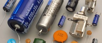
Home » Electrical wiring » Light switches » How to repair a dimmer yourself?
Today, many people use dimmer. The dimmer can fail quite often. Most often this happens when protective devices are not installed in the house. The devices are considered sensitive to voltage surges. If increased loads occur, then the device may simply break.
In this article you will find the main reasons that may affect the performance of the device. You will also find detailed information on how to perform high-quality dimmer repairs yourself.
Causes of dimmer failures
Most often, the cause of failure may be exceeding the maximum permissible load or a short circuit in the load. Excess of load occurs when, for example, lovers of good lighting screw too powerful lamps into chandeliers. Or several lamps are connected through a dimmer, which in total consume too much power.
By the way, when choosing a dimmer, you should select the power with a margin of 30...50%. How to increase the power of a dimmer will be discussed and shown in this article.
A short circuit is possible not only due to faulty wiring. It happens that when light bulbs burn out, a short circuit (short circuit) occurs in them, the nature of which we will not delve into.
In addition, at the moment the incandescent lamp is turned on, a current flows through it, several times higher than the working one. Read more in the article about the resistance of an incandescent lamp.
Illuminated model
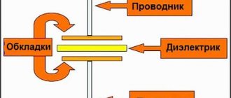
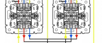
There are light switches equipped with backlighting. The essence of this device is that an LED with a resistor or a miniature neon indicator lamp is mounted parallel to the main contacts. The diagram of this embodiment is shown below:
When the lighting is turned off, current flows through the lighting lamp(s) and the LED with a current-limiting resistor. Its value is too small to light a lamp, but is sufficient to light an LED. Thus, the diode light helps to find the light switch in a dark room. When we turn on the lamp, the contacts bypass the LED, it is de-energized and goes out.
In addition to ease of use, this scheme makes it possible to check the condition of the switch contacts. After all, the backlight circuit is an analogue of the same test lamp with which you can check a regular switch. For example, if you pressed a key, the light did not turn on, and the LED did not stop lighting, then the contacts did not close.
Malfunctions of dimmers on a triac
As a result of a short circuit and overload, a triac usually fails . This is the main malfunction; it occurs in 90% of breakdown cases.
The triac is the main element. Its distinctive features are three terminals and a radiator screwed to the body. The most common models are BT137, BT138, BT139.
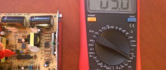
A faulty triac can be detected with a multimeter. If you test the resistance between terminals A1 and A2 (or T1 and T2, the first and second terminals) in ohmmeter mode, it will be from zero to several ohms. Conclusion - the triac has definitely burned out.
There is another case - the triac rings normally (infinite resistance), but the dimmer, however, does not work (the lamp does not light in all positions of the regulator). Only checking will help here, i.e. inclusion in a real circuit.
Replacing the triac will be discussed in detail below.
In addition to a faulty triac, there are other dimmer faults:
- The power tracks of the printed circuit board burn out. This is a consequence of the main malfunction. The paths will have to be restored with jumpers.
- The mechanical integrity of the regulator (potentiometer or variable resistor) is damaged. From frequent and intensive use, no explanation is needed here.
- In dimmers that have a fuse, you must first check it before repairing. Often the manufacturer provides a spare one, which is stored in the same dimmer as the worker. Rational decision. If it had been in a separate bag, it would have definitely gotten lost.
- Mechanical failure of contacts and soldering of the printed circuit board. First of all, soldering the contacts where the wires are screwed. It also happens that electronic elements are simply poorly soldered by the manufacturer.
- Malfunctions of individual elements. First of all - dinistor, then resistors and capacitors.
Advantages
So, we have looked at the design features of the device for turning on lights from Legrand and now we can note what advantages they have. These advantages are:
- ease of use and installation;
- availability of additional functions;
- environmental friendliness;
- reliability;
- wide choice of external design.
As for the cons, the price is a little high for most models. However, it is quite justified, since it corresponds to the quality.
In the future, we will focus on the series of switches that are produced within the walls of the Legrand organization. So, she releases the following series:
- Celiane;
- Galea Life;
- Valena;
- Etika;
- Cariva;
- Kaptika;
- Batibox;
- Quteo;
- Oteo;
- Soliroc;
- Plexo.
Dimmer circuit
Before repairing, let's look at the dimmer circuit. Compared to the previous article about the dimmer, I slightly reworked and clarified the diagram. In the last article I left the scheme the same. But in the new one, I did not change the numbering of parts, so as not to cause confusion.
Dimmer circuit for incandescent lamps using a triac
The dimmer that we will repair has exactly this circuit.
Dimming the non-dimmable
You are commenting as a guest. If you have an account, log in to write on your behalf. Note: Your post will require moderator approval before it will be visible.
ads
- Read before creating a topic!
Messages
TTGO T-Beam v1.0 ESP32 Bluetooth Wi-Fi wireless module LoRa GPS NEO-6M SMA with OLED
Related publications
I made a ripple coefficient meter on Arduino, but I don’t have a reference device at hand to at least approximately calibrate. Please unsubscribe to the thread if anyone has (or can borrow from someone for a while) both an Arduino+Photoresistor (regular, for example GL5528), and a reference factory device, at least inexpensive, for example Radex Lupin, Ecolight, TKA-PKM and etc. Since the photoresistor is still without filters, I think it’s worth trying only on different available LED lamps, but if you also have incandescent lamps, it will not be superfluous for statistics. You can use any Arduino (Nano, Uno, Pro Mini, etc.), I have attached a sketch and a connection diagram, in the terminal (port monitor), the speed is 9600, the measured readings will be displayed every second, I would like to see the test results on different lamps with same distance, for example 20 cm: photoresistor and device. Pulsometer.ino
Dimmer repair procedure
Now I will give an example of how to replace a triac with your own hands, using a drill, soldering iron, and an ordinary toothpick.
The triac can be replaced by unscrewing the radiator and removing the triac from the board. But the radiator is now being riveted. The rivet is much more technologically advanced and cheaper in mass production.
Therefore, we pick up a drill with a drill with a diameter of 3.5...5.5 mm.
1 Drill out the radiator rivet
The arrow shows the direction of the drill.
2 Remove the radiator from the triac
The radiator has been removed, now you need to carefully remove the bad triac, causing minimal damage to the board. Recommended soldering iron power is 25 or 40 W.
3 Unsolder the triac from the board. The triac outputs are designated T1, T2, Gate.
Plus, a soldering iron requires experience and dexterity.
A soldering iron with a power of 60 Watts or more can easily damage the board.
Next, we prepare a place for the new triac, using a wooden toothpick for this:
4 Prepare the holes for the new triac
5 Board is ready
6 Place for a new triac
The sites are stuck together, but that doesn’t matter yet.
And here are the triac friends, next to the DB3 dinistor:
7 New triacs and DB3 dinistor
The triacs (BT139, BT138, BT137) in the photo are all for a voltage of 800 Volts, the maximum operating current is 16, 12, and 8 Amps, respectively.
The datasheet can be downloaded at the end of the article.
Now we insert a new part into these through holes:
8 Triac is sealed
9 Trimming the legs (conclusions))
The jumper was unsuccessful, it was necessary to use thinner wires...
We carefully check the soldering to ensure there is no short circuit between the contact pads.
Next, we mount the radiator. At home, it is cheaper and more technologically advanced to use a M3 screw, washer and nut.
10 All that remains is to screw on the radiator
Now all that remains is to check the operation in a real connection circuit. Let me remind you that the dimmer is turned on in the same way as a regular switch:
Turning on the light bulb through the brightness control.
For the test circuit, I use a light bulb of any power in the socket, a wire with a plug, and a Vago 222 terminal block.
Methods for attaching mirrors to the wall
So, you bought a mirror, but don’t know how to hang it on the wall? Follow our recommendations carefully and you can hang a mirror yourself without breaking the bank. Frameless mirrors are very popular now, and we will deal with this case first.
For all types of installation, prepare the following tools:
First of all, it is important for us that the mirror hangs evenly. To do this we will use a level. The level may be large, or it may be small. By the way, modern technologies make it possible to use even a virtual building level for leveling. To do this, download the appropriate application from PlayMarket or AppStore.
Also, it will be more convenient to install with a suction cup handle for glass. With its help, you can carry the mirror without fear of breaking the canvas. In addition, in all methods except gluing, you will need a screwdriver with a drill of the required thickness for your base.
Mirror glue
The advantage of the gluing method is that you do not need to drill holes in the wall. The adhesive composition will perfectly hold the mirror even on surfaces such as tiles and laminated MDF. At the same time, keep in mind that the wall on which the product will be located must be level. In addition, ordinary superglue or sealant will not be suitable for these purposes, since it contains substances that corrode the reflective layer of the mirror.
If you are gluing a mirror to a wooden surface, it is better to use a combination of glue and several strips of double-sided tape.
Step-by-step algorithm of actions:
- From the section of the wall on which the mirror will hang, it is necessary to remove decorative finishing - wallpaper, paint or plaster. Cover the wall with primer, dry and degrease.
- Also degrease the back surface of the mirror. Apply glue according to the diagram in the illustration above. For stronger adhesion, apply glue to the placement site as well.
- Together with an assistant, quickly and carefully lift the mirror and install it in its place.
- Secure it from the outside with masking tape. After 3 days, the mirror will be completely dry and the insurance can be removed.
Mirror holders
Installation on holders is good because the mirror can be removed and moved to another place at any time. In addition, the holders are best suited for mounting on uneven walls.
In this method, holders are first mounted into the wall, and then the canvas itself is inserted into them. It is more convenient to start installation from the lower holders, because they are the very base that will hold the mirror.
Step-by-step algorithm of actions:
- Place the mirror against the wall. Level it using a level and use a pencil to mark 4 points into which the fasteners will be screwed. Typically, two holders are used at the bottom and two on the sides of the mirror.
- Using a drill, drill the required holes in the wall.
- Insert the screws into the special holes on the fasteners. Attach the holders to the wall using a screwdriver.
- Together with an assistant, carefully lift the mirror and install it in its place. Cover the fastening area with decorative covers. Ready!
Two more dimmers. Appearance of printed circuit boards.
Bonus – more photos:
11 The track on the board is burned out
12 Dimmer board
13 Dimmer board, view of the triac
Resistors are color coded. Did you learn as I recommended?
14 markings on the radiator
Broken dimmer, triac needs to be replaced
Broken dimmer, triac needs to be replaced
Peculiarities
To have a complete understanding of symmetrical thyristors, it is necessary to talk about their strengths and weaknesses. The first include the following factors:
- relatively low cost of devices;
- long service life;
- lack of mechanics (that is, moving contacts that are sources of interference).
The disadvantages of the devices include the following features:
The need for heat removal is approximately at the rate of 1-1.5 W per 1 A, for example, at a current of 15 A, the power dissipation value will be about 10-22 W, which will require an appropriate radiator. For ease of fastening to it for powerful devices, one of the terminals has a thread for a nut.
Triac with radiator mount
- Devices are subject to transients, noise and interference;
- High switching frequencies are not supported.
The last two points require a little clarification. In the case of high switching speed, there is a high probability of spontaneous activation of the device. Interference in the form of a voltage surge can also lead to this result. To protect against interference, it is recommended to bypass the device with an RC circuit.
RC circuit to protect the triac from interference
In addition, it is recommended to minimize the length of the wires leading to the controlled output, or alternatively use shielded conductors. It is also practiced to install a shunt resistor between the T1 terminal (TE1 or A1) and the control electrode.
Similarities between dimmers and lamp protection units
I described in detail the lamp protection blocks that smoothly turn on the brightness of the lamps in my articles about the design and connection and diagram of such blocks.
The difference between dimmers and BZ is only in the control method. In protection blocks, the triac is controlled by a controller according to the program. And the program can be anything, up to a wave-like change in brightness. Any analog or digital signal can be controlled. There would be demand.
If you are interested in what I write about, subscribe to receive new articles and join the group on VK!
Why is verification needed?
In the process of repairing or assembling a new circuit, it is impossible to do without electrical parts. One of these parts is a triac. It is used in alarm circuits, light controllers, radio devices and many branches of technology. Sometimes it is reused after dismantling non-working circuits, and it is not uncommon to encounter an element whose markings have been lost due to long-term use or storage. It happens that new parts need to be checked.
How can you be sure that the triac installed in the circuit is really working, and in the future you will not need to spend a lot of time debugging the operation of the assembled system?
To do this, you need to know how to test a triac with a multimeter or tester. But first you need to understand what this part is and how it works in electrical circuits.
In fact, a triac is a type of thyristor. The name is made up of these two words - “symmetrical” and “thyristor”.
Types of thyristors
Thyristors are usually called a group of semiconductor devices (triodes) capable of passing or not passing electric current in a given mode and at certain periods of time. This creates conditions for the circuit to operate in accordance with its functions.
The operation of thyristors is controlled in two ways:
- by applying a voltage of a certain value to open or close the device, as in dinistors (diode thyristors) - two-electrode devices;
- by applying a current pulse of a certain duration or magnitude to the control electrode, as in thyristors and triacs (triode thyristors) - three-electrode devices.
Based on the principle of operation, these devices are divided into three types.
The dinistors open when the voltage reaches a certain value between the cathode and the anode and remain open until the voltage decreases again to the set value. When open, they operate on the principle of a diode, passing current in one direction.
SCRs open when current is applied to the control electrode contact and remain open when there is a positive potential difference between the cathode and anode. That is, they are open as long as there is voltage in the circuit. This is ensured by the presence of a current whose strength is not lower than one of the parameters of the thyristor - the holding current. When open, they also operate on the principle of a diode.
Triacs are a type of thyristors that pass current in two directions when in the open state. In essence, they represent a five-layer thyristor.
Lockable thyristors are SCRs and triacs that close when a current of opposite polarity is applied to the control electrode contact than the one that caused it to open.