Description
The calibrator includes traditional components and devices:
— reference voltage source (VS);
— digital-to-analog resistive converter (DAC), providing DC voltage conversion, the bit depth of which is determined by the required resolution of the calibrator (sixteen binary digits);
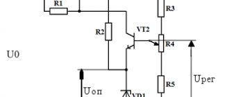
- a high-voltage amplifier operating at the playback limits of “1 V” and “10 V” as a buffer with a gain of 1 and operating at the limits of “100 V” and “1000 V” with a gain of 10 and 100 times, respectively.
The current calibrator mode is implemented by a circuit based on a U/I amplifier, the negative feedback circuit of which includes a load. The circuit converts voltage into current. The conversion coefficient is determined by the value of the reference resistor and the input voltage (from 0 to 0.2 V).
Structurally, the calibrator is a closed case with controls and a digital display on the front panel, where the output terminals are also located. On the rear panel there is a network connector with a fuse, a power switch, and a grounding contact.
Metrological characteristics depend on the stability of the parameters of the electronic radio elements used in the calibrator and are ensured by its circuit solutions. The calibrator has no components that require adjustment during operation.
A general view of the calibrator is shown in Figure 1. A diagram of sealing against unauthorized access, designation of places for applying verification marks in Figure 2.
The verification mark in the form of a sticker is applied to the free space on the front panel
Figure 2 - Scheme of sealing against unauthorized access, designation of places
applying verification marks
Differences
Laboratory calibrators of electrical quantities differ from other electrical measuring devices in their increased level of accuracy. A number of models are equipped with microprocessor control and a set of interfaces for exchanging data with computers. These devices have increased levels of productivity, which automates workflows and simplifies reporting.
Calibrators differ from each other:
- A set of measured and generated parameters;
- Range of reproducible parameters;
- Accuracy and accuracy class;
- Number of working channels;
- Availability of analytical and other functions;
- Design features - for use in the laboratory or in the field.
Software
The calibrator software is written into the microcontroller control program memory at the production stage and cannot be changed during the operation of the calibrator.
The software does not affect the metrological characteristics and sets the internal configuration of the calibrator's components, while ensuring that its operating mode corresponds to the mode specified by the operator.
There is no interface for pairing the calibrator with other digital devices, which makes it impossible to modify its software.
The software protection level is “high” in accordance with R 50.2.077-2014. Software identification data is given in Table 1.
Table 1 - Software identification data
| Identification data (signs) | Meaning |
| Software identification name | n419.hex |
| Software version number (identification number) | 1.1 |
| Digital ID for calibration data and software* | — |
| Algorithm for calculating the digital software identifier* | — |
| * Columns are not filled in due to the lack of software affecting the metrological characteristics. | |
Table 2 — Metrological characteristics of the calibrator
| Characteristic name | Meaning |
| DC voltage reproduction range at reproduction limits (IP), V: 1 V 10 V 100 V 1000 V | from 0 to 0.99999 incl. from 1 to 9.9999 inclusive. from 10 to 99.999 inclusive. from 100 to 999.99 inclusive. |
| Discreteness of setting the DC voltage at the reproduction limits (IP), mV: 1 V 10 V 100 V 1000 V | 0,01 0,1 1 10 |
| Limits of permissible relative error of DC voltage reproduction within limits (Ip), ± (% of Im + % of Ip) 1V, 10V,100V, 1000V | 0,05 + 0,002 |
| Range of reproduction of direct current strength at the reproduction limit (1p) 200 mA, A, not less: | from 0 to 0.19999 incl. |
| Discreteness of setting the DC current at the reproduction limit (1p) 200 mA, µA | 10 |
| Limits of permissible relative error of direct current at the reproduction limit (1p) 200 mA, ±(% of 1x + % of 1p): | 0,06 + 0,01 |
| Time to establish output readings with normalized error, s, no more | 10 |
| Time to establish the operating mode (warm-up), min, no more | 30 |
| Operating conditions: | |
| — ambient air temperature, °C | from + 10 to + 35 incl. |
| — relative humidity of ambient air at temperatures up to + 25 °C, %, no more | 80 |
| — supply voltage, V | from 198 to 242 incl. |
| — industrial network frequency, Hz Notes 1 IP (1p) - voltage reproduction limits (power t 2 Their (1x) - reproducible values of voltage (force | from 48 to 52 incl. oka). current). |
| Characteristic name | Meaning |
| Maximum load current at rated value according to | |
| errors at reproduction limits (ip), mA, not less: | |
| 1 V | Limited Rout=0.07 Ohm |
| 10 V, 100 V | 50 |
| 1000 V | 5 |
| RMS value of pulsations at the output of the caliber - | |
| torus, in the frequency band up to 5 kHz, within the playback limits | |
| (ip), mV, no more: | |
| 1 V | 0,2 |
| 10 V | 0,5 |
| 100 V | 1 |
| 1000 V | 5 |
| Format for presenting numerical information - values | 5 decimal places |
| running voltage or current | |
| Sinusoidal test voltage value, | |
| frequency 50 Hz, maintained by electrical insulation between | |
| between the mains circuits of the calibrator and the housing without breakdown and | |
| surface covering, B, not less | 1500 |
| The value of the electrical insulation resistance between the circuits | |
| calibrator power supply and its housing: | |
| — under normal conditions of use, MOhm, not less | 20 |
| — at elevated temperature MOhm, not less | 5 |
| The value of electrical resistance between the grounding | 0,5 |
| contact of the power plug and the device body, Ohm, no more | |
| Time of continuous operation in working conditions, h, not less | 24 |
| Power consumed by the calibrator from the power supply at | |
| rated voltage, VA, no more | 60 |
| Requirements for the stability and strength of the calibrator to WHO | |
| exposure to climatic factors and mechanical influences | group 2 according to GOST 22261-94 |
| Parameters of reliability, durability and maintainability | |
| calibrator: | |
| — mean time between failures, h, not less | 20000 |
| — gamma-percentage resource, at g = 90%, h, not less | 20000 |
| — gamma-percentage service life, at g = 80%, years, not less | 15 |
| — gamma-percentage shelf life, at g = 80% | |
| for heated storage facilities, years, not less | 10 |
| for unheated storages, years, not less | 5 |
| — average time to restore working condition, | |
| min, no more | 60 |
| — probability of no hidden failures within 24 months | |
| with an average utilization rate of 0.23, no less | 0,9 |
| Characteristic name | Meaning |
| Calibrator weight, kg, no more | 3,5 |
| Weight of the calibrator in consumer packaging, kg, no more | 5,5 |
| Overall dimensions of the calibrator (length x width x height), mm, no more | 257x308x102 |
Table 4 - Permissible voltage values of the IRP
| Frequency band, MHz | Voltage Uc, dB (relative to 1 µV) | |
| Quasi-peak value | Average value | |
| From 0.15 to 0.5 incl. | From 66 to 56 inclusive. | From 56 to 46 incl. |
| St. 0.5 to 5 incl. | 56 | 46 |
| St. 5 to 30 incl. Notes 1 At the cutoff frequency the norm is m 2 In the frequency band from 0.15 to 0.5 MHz include: Uc = 66 - 19.1lg f / 0.15 for quasi-peak average values, where f is the measurement frequency in meg | 60 lower voltage value permissible values of new values and Uc = 56 hertz. | 50 NIIA IRP. voltage calc - 19.1lg f / 0.15 for |
Table 5 - Permissible field strength values of the IRP
| Frequency band, MHz | Field strength, dB (relative to 1 µV/m), quasi-peak value |
| From 30 to 230 incl. | 30 |
| St. 230 to 1000 incl. Note - at the boundary frequency of the IRP field. | 37 the norm is a lower tension value |
Completeness
The complete set of the calibrator is indicated in Table 6.
Table 6 — Contents of the calibrator delivery kit
| Designation | Name | Col. | Note |
| MEASURE.411572.002 | Constant voltage and current calibrator N4-19 | 1 | |
| Spare parts and accessories (SPTA) | |||
| MEASURE.685061.008 | Connecting cable | 1 | Black, pin - pin |
| MEASURE.685061.008-01 | Connecting cable | 1 | White, pin - pin |
| MEASURE.685061.010 | Connector | 1 | Red, pin - pin |
| MEASURE.685061.010-01 | Connector | 1 | Black, pin - pin |
| Fingerguard Shrouded 446-967 red | Crocodile | 1 | Red |
| Designation | Name | Col. | Note |
| Fingerguard Shrouded 446-967 black | Crocodile | 1 | Black |
| OYu0.481.005 TU | Fuse link VP2B-1V 2.0A 250 V | 2 | Network |
| H05VV-F | Connecting cord | 1 | Network |
| BESKIN 1901/1 | Medium case, black (includes shoulder strap) | 1 | For storage and transportation |
| Operational documentation | |||
| MERA.411572.001RE | Constant voltage and current calibrator N4-19. Manual. | 1 | |
| MEASURE.411572.001FO | Calibrator N4-19 constant voltage and current. Form | 1 | |
calibrators
Attention!!! Delivery of ALL devices that are listed on the website takes place throughout the ENTIRE territory of the following countries: Russian Federation, Ukraine, Republic of Belarus, Republic of Kazakhstan and other CIS countries.
In Russia there is an established delivery system to the following cities: Moscow, St. Petersburg, Surgut, Nizhnevartovsk, Omsk, Perm, Ufa, Norilsk, Chelyabinsk, Novokuznetsk, Cherepovets, Almetyevsk, Volgograd, Lipetsk Magnitogorsk, Tolyatti, Kogalym, Kstovo, Novy Urengoy, Nizhnekamsk, Nefteyugansk, Nizhny Tagil, Khanty-Mansiysk, Yekaterinburg, Samara, Kaliningrad, Nadym, Noyabrsk, Vyksa, Nizhny Novgorod, Kaluga, Novosibirsk, Rostov-on-Don, Verkhnyaya Pyshma, Krasnoyarsk, Kazan, Naberezhnye Chelny, Murmansk, Vsevolozhsk, Yaroslavl, Kemerovo, Ryazan, Saratov, Tula, Usinsk, Orenburg, Novotroitsk, Krasnodar, Ulyanovsk, Izhevsk, Irkutsk, Tyumen, Voronezh, Cheboksary, Neftekamsk, Veliky Novgorod, Tver, Astrakhan, Novomoskovsk, Tomsk, Prokopyevsk, Penza, Urai, Pervouralsk , Belgorod, Kursk, Taganrog, Vladimir, Neftegorsk, Kirov, Bryansk, Smolensk, Saransk, Ulan-Ude, Vladivostok, Vorkuta, Podolsk, Krasnogorsk, Novouralsk, Novorossiysk, Khabarovsk, Zheleznogorsk, Kostroma, Zelenogorsk, Tambov, Stavropol, Svetogorsk, Zhigulevsk , Arkhangelsk and other cities of the Russian Federation.
In Ukraine there is an established delivery system to the following cities: Kiev, Kharkov, Dnepr (Dnepropetrovsk), Odessa, Donetsk, Lvov, Zaporozhye, Nikolaev, Lugansk, Vinnitsa, Simferopol, Kherson, Poltava, Chernigov, Cherkassy, Sumy, Zhitomir, Kirovograd, Khmelnitsky , Rivne, Chernivtsi, Ternopil, Ivano-Frankivsk, Lutsk, Uzhgorod and other cities of Ukraine.
In Belarus there is an established delivery system to the following cities: Minsk, Vitebsk, Mogilev, Gomel, Mozyr, Brest, Lida, Pinsk, Orsha, Polotsk, Grodno, Zhodino, Molodechno and other cities of the Republic of Belarus.
In Kazakhstan, there is an established delivery system to the following cities: Astana, Almaty, Ekibastuz, Pavlodar, Aktobe, Karaganda, Uralsk, Aktau, Atyrau, Arkalyk, Balkhash, Zhezkazgan, Kokshetau, Kostanay, Taraz, Shymkent, Kyzylorda, Lisakovsk, Shakhtinsk, Petropavlovsk, Rider, Rudny, Semey, Taldykorgan, Temirtau, Ust-Kamenogorsk and other cities of the Republic of Kazakhstan.
Devices are supplied to the following countries: Azerbaijan (Baku), Armenia (Yerevan), Kyrgyzstan (Bishkek), Moldova (Chisinau), Tajikistan (Dushanbe), Turkmenistan (Ashgabat), Uzbekistan (Tashkent), Lithuania (Vilnius), Latvia (Riga) ), Estonia (Tallinn), Georgia (Tbilisi).
All text and graphic information on the site is for informational purposes only. Color, shade, material, geometric dimensions, weight, content, delivery set and other parameters of the product presented on the website may vary depending on the production batch and year of manufacture. For more detailed information, please contact the sales department.
Verification
carried out according to the document MERA.411572.001 RE “Calibrator of constant voltage and current N4-19. Operating manual", section 4 "Verification", approved by the Federal Budgetary Institution "Krasnodar CSM" on October 5, 2016.
The main means of verification are given in Table 7.
Table 7 - Main means of verification
| Name | Type of measuring instruments | Registration number |
| 1 | 2 | 3 |
| Working standard 3rd category according to GOST 8.027-2001 | — | — |
| Working standard of the 3rd category by order of Rosstandart dated February 15, 2016. No. 146 | — | — |
| Multimeter (2 pcs.) | B7-64/1 | 16668-97 |
| Electrical resistance coil | P321 | 1162-58 |
| Multi-valued measure of electrical resistance of direct current | P3026 | 8478-81 |
It is allowed to use similar verification means that ensure the determination of the metrological characteristics of calibrators with the required accuracy.
Verification marks are applied to the screws securing the upper and lower covers of the calibrator housing. The verification mark in the form of a sticker is applied to the free space on the front panel.