05/08/2020 632 Generators
Author:Ivan
Depending on the device and operating principle, generator voltage relay regulators in a car are divided into several types: built-in, external, three-level and others. Theoretically, such a device can be made independently; the simplest and cheapest option in terms of implementation is to use a shunt device.
[Hide]
Purpose of the relay regulator
The generator voltage regulator relay is designed to stabilize the current in the installation. When the engine is operating, the voltage in the vehicle's electrical system must be at the same level. But since the crankshaft rotates at different speeds and the engine speed is not the same, the generator unit produces different voltages. Without adjusting this parameter, malfunctions in the functioning of the electrical equipment and devices of the machine may occur.
Interconnection of car current sources
Any car uses two power sources:
- Battery - required to start the power unit and primary excitation of the generator set. The battery consumes and stores energy when recharging.
- Generator. Designed for power and needed to generate energy regardless of speed. The device allows you to replenish the battery charge when operating at high speeds.
In any electrical network, both nodes must be working. If the DC generator fails, the battery will last no more than two hours. Without a battery, the power unit, which drives the rotor of the generator set, will not start.
The LR West channel talked about electrical faults in Land Rover cars, as well as the relationship between the battery and generators.
Voltage regulator tasks
Tasks performed by an electronic adjustable device:
- change in current value in the excitation winding;
- the ability to withstand a range of 13.5 to 14.5 volts in the electrical network, as well as at the battery terminals;
- turning off the power to the field winding when the power unit is turned off;
- battery charging function.
“People's Auto Channel” spoke in detail about the purpose, as well as the tasks performed by the voltage regulator device in a car.
Generator operation
When the rotor begins to rotate, some voltage appears at the generator output. And it is supplied to the excitation winding through a control element. It is also worth noting that the generator set output is connected directly to the battery. Therefore, voltage is constantly present on the excitation winding. When the rotor speed increases, the voltage at the generator set output begins to change. A voltage regulator relay from a Valeo generator or any other manufacturer is connected to the generator output.
In this case, the sensor detects the change, sends a signal to a comparing device, which analyzes it, comparing it with a given parameter. Next, the signal goes to the control device, from which it is supplied to the actuator. The regulatory body is able to reduce the value of the current that flows to the rotor winding. As a result, the voltage at the generator set output is reduced. In a similar way, the mentioned parameter is increased in the event of a decrease in rotor speed.
Types of relay regulators
There are several types of automotive relay regulators:
- external - this type of relay allows you to increase the maintainability of the generator unit;
- built-in - installed in the rectifier plate or brush assembly;
- changing in minus direction - equipped with an additional cable;
- regulated by plus - characterized by a more economical connection scheme;
- for installation in AC units - the voltage cannot be adjusted when applied to the excitation winding, since it is installed in the generator;
- for direct current devices - relay regulators have the function of cutting off the battery when the engine is not running;
- two-level relays - today they are practically not used; they are adjusted using springs and a lever;
- three-level - equipped with a comparison module circuit, as well as a matching signaling device;
- multi-level - equipped with 3-5 additional resistor elements, as well as a control system;
- transistor samples - not used on modern vehicles;
- relay devices - characterized by more improved feedback;
- relay-transistor - have a universal circuit;
- microprocessor relays - characterized by their small size, as well as the ability to smoothly change the lower or upper operating threshold;
- integral - installed in brush holders, so they change when they wear out.
DC relay regulators
In such units, the connection diagram looks more complex. If the car is stationary and the engine is not running, the generator unit must be disconnected from the battery.
When performing a relay test, you must ensure that you have three options:
- battery cut-off when the vehicle is parked;
- limitation of the maximum current parameter at the unit output;
- possibility of changing the voltage parameter for the winding.
AC relay regulators
Such devices are characterized by a more simplified testing scheme. The car owner needs to diagnose the voltage level on the excitation winding, as well as at the output of the unit.
If an alternating current generator is installed in the car, then it will not be possible to start the engine “from a pusher”, unlike a direct current unit.
Built-in and external relay regulators
The procedure for changing the voltage value is carried out by the device at a specific installation location. Accordingly, the built-in regulators influence the generator unit. And the external type of relay is not connected to it and can be connected to the ignition coil, then its work will only be aimed at changing the voltage in this area. Therefore, before performing diagnostics, the car owner must make sure that the part is connected correctly.
The “Sovering TVi” channel spoke in detail about the purpose and operating principle of this type of device.
Two-level
The operating principle of such devices is as follows:
- Current flows through the relay.
- As a result of the formation of a magnetic field, the lever is attracted.
- A spring with a specific force is used as a comparing element.
- When the voltage increases, the contact elements open.
- Less current is supplied to the field winding.
In VAZ cars, mechanical two-level devices were previously used for regulation. The main disadvantage was the rapid wear of structural components. Therefore, instead of mechanical ones, electronic regulators began to be installed on these machine models.
These parts were based on:
- voltage dividers, which were assembled from resistor elements;
- A zener diode was used as a reference part.
Due to the complex wiring diagram and ineffective voltage level control, this type of device has become less common.
Three-level
This type of regulators, like multi-level ones, are more advanced:
- The voltage is supplied from the generator device to a special circuit and passes through a divider.
- The received data is processed, the actual voltage level is compared with the minimum and maximum values.
- The mismatch pulse changes the current parameter that is supplied to the excitation winding.
Three-level devices with frequency modulation do not have resistance, but the frequency of operation of the electronic key in them is higher. Special logic circuits are used for control.
Control by minus and plus
The circuits for the negative and positive contacts differ only in connection:
- when installed in the positive gap, one brush is connected to ground, and the second goes to the relay terminal;
- if the relay is installed in the minus gap, then one brush element must be connected to the plus, and the second - directly to the relay.
But in the second case, another cable will appear. This is due to the fact that these relay modules belong to the class of active type devices. For its operation, a separate power supply is required, so the plus is connected individually.
Photo gallery “Types of generator voltage regulator relays”
This section presents photos of some types of devices.
Remote device type
Built-in regulator
Transistor-relay type
Integral device
Device for DC generator
AC control device
Two-level device type
Three-level control device
- Currently 2.60/5
Rating 2.6 /5 (122 votes)
The voltage regulator maintains the on-board network voltage within specified limits in all operating modes when changing the generator rotor speed, electrical load, and ambient temperature. In addition, it can perform additional functions - protect the elements of the generator set from emergency conditions and overload, automatically include an excitation winding circuit or an alarm system for the emergency operation of the generator set into the on-board network.
All voltage regulators operate on the same principle. The generator voltage is determined by three factors - the rotor speed, the current supplied by the generator to the load, and the amount of magnetic flux created by the field winding current. The higher the rotor speed and the lower the load on the generator, the higher the generator voltage. Increasing the current in the excitation winding increases the magnetic flux and with it the generator voltage, decreasing the excitation current reduces the voltage.
All voltage regulators, domestic and foreign, stabilize the voltage by changing the excitation current. If the voltage increases or decreases, the regulator accordingly reduces or increases the excitation current and brings the voltage within the desired limits.
The block diagram of the voltage regulator is shown in Fig. 1.
Regulator 1 contains a measuring element 5, a comparison element 3 and a regulating
element 4. The measuring element perceives the voltage of generator 2 Ud and converts it into a signal Umeas., which in the comparison element is compared with the reference value Uet.
If the value of Umeas. differs from the reference value Uet, a signal Uo appears at the output of the measuring element, which activates the control element, which changes the current in the field winding so that the generator voltage returns to the specified limits.
Thus, the voltage regulator must be supplied with generator voltage or voltage from another location on the on-board network where its stabilization is necessary, for example, from a battery, and the generator excitation winding must also be connected. If the functions of the regulator are expanded, then the number of its connections in the circuit increases.
The sensitive element of electronic voltage regulators is the input voltage divider. From the input divider, the voltage is supplied to the comparison element, where the role of the reference value is usually played by the stabilization voltage of the zener diode. The zener diode does not pass current through itself at a voltage below the stabilization voltage and breaks through, i.e. begins to pass current through itself if the voltage across it exceeds the stabilization voltage. The voltage on the zener diode remains practically unchanged.
The current through the zener diode turns on an electronic relay, which switches the excitation circuit in such a way that the current in the excitation winding changes in the desired direction. In vibration and contact-transistor regulators, the sensitive element is presented in the form of a winding of an electromagnetic relay, the voltage to which, however, can also be supplied through an input divider, and the reference value is the tension force of the spring, which counteracts the attractive force of the electromagnet.
Switching in the field winding circuit is carried out by relay contacts or, in a contact-transistor regulator, by a semiconductor circuit controlled by these contacts.
A feature of automotive voltage regulators is that they carry out discrete voltage regulation by turning on and off the excitation winding in the power circuit (in transistor regulators) or in series with the winding of an additional resistor (in vibration and contact-transistor regulators), while the relative duration of switching on the winding changes or an additional resistor.
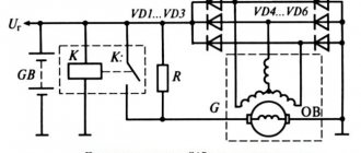
Since vibration and contact-transistor regulators are of only historical interest, and electronic transistor regulators are currently used in domestic and foreign generator sets, it is convenient to consider the principle of operation of a voltage regulator using the example of a simple circuit close to the domestic voltage regulator YA112A1 and the EE14V3 regulator from BOSCH ( Fig. 2).
Regulator 2 in the diagram works in conjunction with generator 1, which has an additional
field winding rectifier. To understand the operation of the circuit, we should remember that, as shown above, the zener diode does not pass current through itself at voltages below the stabilization voltage. When the voltage reaches this value, the zener diode breaks through and current begins to flow through it.
Transistors pass current between the collector and emitter, i.e. open if current flows in the base-emitter circuit, and do not allow this current to pass through, i.e. closed if the base current is interrupted.
Voltage is supplied to the zener diode VD1 from the output of generator D through a voltage divider across resistors R1, R2. While the generator voltage is low, and at the zener diode it is lower than the stabilization voltage, the zener diode is closed, no current flows through it, and, consequently, in the base circuit of transistor VT1, transistor VT1 is closed. In this case, the current through resistor R6 from pin D enters the base circuit of transistor VT2, it opens, and current begins to flow through its emitter-collector junction in the base of transistor VT3, which also opens. In this case, the excitation winding of the generator is connected to the power circuit through the emitter-collector junction VT3.
The connection of transistors VT2, VT3, in which their collector terminals are combined, and the base circuit of one transistor is powered from the emitter of the other, is called a Darlington circuit. With this connection, both transistors can be considered as one composite transistor with a high gain. Typically, such a transistor is made on a single silicon crystal.
If the generator voltage increases, for example, due to an increase in the rotation speed of its rotor, then the voltage at the zener diode VD1 also increases. When this voltage reaches the value of the stabilization voltage, the zener diode VD1 breaks through, the current through it begins to flow into the base circuit of the transistor VT1, which opens and, with its emitter-collector transition, short-circuits the base output of the composite transistor VT2, VTZ to ground. The composite transistor closes, breaking the power supply circuit of the field winding. The excitation current drops, the generator voltage decreases, the zener diode VD2 and transistor VT1 close, the composite transistor VT2, VTZ opens, the excitation winding is reconnected to the power circuit, the generator voltage increases, etc., the process repeats.
Thus, the generator voltage is adjusted by the regulator discretely by changing the relative time of switching on the excitation winding of the power circuit. In this case, the current in the excitation winding changes as shown in Fig. 3.
If the generator rotation speed has increased or its load has decreased, the winding turn-on time decreases; if the rotation speed decreases or the load increases, it increases.
In the regulator circuit shown in Fig. 2 there are elements characteristic of the circuits of all voltage regulators used on cars. Diode VD2, when closing the composite transistor VT2, VT3, prevents dangerous voltage surges arising from an open circuit in the excitation winding with significant inductance. In this case, the field winding current can be closed through this diode, and dangerous voltage surges do not occur. Therefore, diode VD2 is called a quenching diode.
Resistance R3 is the hard feedback resistance. When the composite transistor VT2, VT3 is opened, it turns out to be connected in parallel to the resistance R2 of the voltage divider. In this case, the voltage on the zener diode VD2 decreases sharply, which speeds up the switching of the regulator circuit and increases the frequency of this switching. This has a beneficial effect on the voltage quality of the generator set.
Capacitor C1 is a kind of filter that protects the regulator from the influence of voltage pulses at its input. In general, capacitors in the regulator circuit either prevent this circuit from entering an oscillatory mode and the possibility of extraneous high-frequency interference influencing the operation of the regulator, or they speed up the switching of transistors. In the latter case, the capacitor, charging at one moment in time, is discharged onto the base circuit of the transistor at another moment, accelerating the switching of the transistor with an inrush of discharge current and, therefore, reducing power losses in it and its heating.
From Fig. Figure 2 clearly shows the role of the lamp for monitoring the operating condition of the HL generator set. When the internal combustion engine is not running, closing the contacts of the ignition switch SA allows current from the battery GA to flow through this lamp into the excitation winding of the generator. This ensures the initial excitation of the generator. At the same time, the lamp lights up, signaling that there is no break in the excitation winding circuit.
After starting the engine, almost the same voltage appears at the generator terminals D and “+” and the lamp goes out. If the generator set does not develop voltage while the car engine is running, the HL lamp continues to light in this mode, which is a signal that the generator set has failed or the drive belt has broken.
The introduction of resistor R into the generator set helps to expand the diagnostic capabilities of the HL lamp. With this resistor present, if the field winding circuit opens while the car engine is running, the HL lamp will light up.
For its reliable operation, the battery requires that as the temperature of the electrolyte decreases, the voltage supplied to the battery from the generator set increases slightly, and as the temperature rises, it decreases.
To automate the process of changing the level of the maintained voltage, a sensor is used, placed in the battery electrolyte and connected to the voltage regulator circuit. In the simplest case, thermal compensation in the regulator is selected in such a way that, depending on the temperature of the cooling air entering the generator, the generator set voltage changes within specified limits.
In the considered voltage regulator circuit, as in all regulators of a similar type, the switching frequency in the field winding circuit changes as the operating mode of the generator changes. The lower limit of this frequency is 25-50 Hz. However, there is another type of electronic regulator circuits in which the switching frequency is strictly specified. Regulators of this type are equipped with a pulse-width modulator (PWM), which provides the specified switching frequency.
The use of PWM reduces the influence on the operation of the regulator of external influences, for example, the level of ripple of the rectified voltage, etc.
Currently, more and more foreign companies are switching to the production of generator sets without an additional rectifier. To automatically prevent the battery from discharging when the car engine is not running, a generator phase is inserted into this type of regulator.
Regulators, as a rule, are equipped with PWM, which, for example, when the engine is not running, switches the output transistor to an oscillatory mode, in which the current in the field winding is small and amounts to fractions of an ampere.
After starting the engine, the signal from the generator phase output switches the regulator circuit to normal operation. In this case, the regulator circuit also controls the lamp for monitoring the operating condition of the generator set.
Related items
- Voltage ranges of domestically produced automotive generator sets
Operating principle of the relay regulator
The presence of a built-in resistor device, as well as special circuits, makes it possible for the regulator to compare the voltage parameter produced by the generator. If the value is too high, the controller is switched off. This allows you to prevent overcharging of the battery and failure of electrical equipment that is powered from the network. Problems with the device will damage the battery.
Switch winter and summer
The generating device operates stably regardless of the ambient temperature and season. When its pulley is set in motion, current is generated. But in the cold season, the internal structural elements of the battery may freeze. Therefore, the battery charge is restored worse than in the heat.
The switch for changing the operating season is located on the relay body. Some models are equipped with special connectors; you need to find them and connect the wires in accordance with the diagram and symbols marked on them. The switch itself is a device thanks to which the voltage level at the battery terminals can be increased to 15 volts.
Checking an Individual Regulator
Checking the voltage regulator of the G-222 generator: 1 - battery; 2 - voltage regulator; 3 - control lamp.
As a rule, separate voltage regulators were installed on old cars, including domestic VAZs. But some manufacturers continue to do this to this day. The verification process is similar. To do this, you need to have a power supply with a voltage regulator, a 12 V light bulb, a multimeter and a directly tested regulator.
To check, you need to assemble the circuit shown in the figure. The process itself is similar to the one above. In normal condition (at a voltage of 12 V), the light bulb lights up. When the voltage value increases to 14.5 V, it goes out, and when it decreases, it lights up again. If during the process the lamp lights up or goes out at other values, it means that the regulator has failed.
Checking relay type 591.3702-01
Relay test diagram type 591.3702-01
You can also still find a voltage regulator of type 591.3702-01, which was installed on rear-wheel drive VAZs (from VAZ 2101 to VAZ 2107), GAZ and Moskvich. The device is mounted separately and installed on the body. In general, the test is similar to that described above, but the differences are in the contacts used.
In particular, it has two main contacts - “67” and “15”. The first of them is a minus, and the second is a plus. Accordingly, to check it is necessary to assemble the circuit shown in the figure. The verification principle remains the same. In normal condition, at a voltage of 12 V, the light bulb lights up, and when the corresponding value increases to 14.5 V, it goes out. When the value returns to its original value, the light comes on again.
A classic regulator of this type is a device of the PP-380 brand, installed on VAZ 2101 and VAZ 2102 cars. We provide reference data regarding this regulator.
| Adjustable voltage at regulator and ambient temperature (50±3)° C, V: | |
| at the first stage | no more than 0.7 |
| on the second stage | 14,2 ± 0,3 |
| Resistance between plug “15” and ground, Ohm | 17,7 ± 2 |
| Resistance between plug “15” and plug “67” with open contacts, Ohm | 5,65 ± 0,3 |
| Air gap between armature and core, mm | 1,4 ± 0,07 |
| Distance between second stage contacts, mm | 0,45 ± 0,1 |
Testing a three-level relay
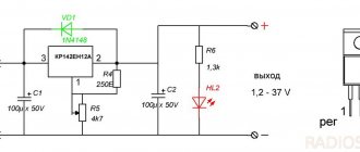
Regulated power supply
Some car owners install on their cars, instead of standard “chocolate bars,” three-level relays, which are technologically more advanced. Their difference is the presence of three voltage levels at which the battery power is cut off (for example, 13.7 V, 14.2 V and 14.7 V). The appropriate level can be set manually using a special regulator.
Such relays are more reliable and allow flexible adjustment of the cutoff voltage level. As for checking such a regulator, it is completely similar to the procedures described above. Just do not forget about the value that is set on the relay, and accordingly, check it with a multimeter.
Generator check
There is one method by which you can check the performance of a car generator equipped with a regulator relay 591.3702-01 with diagnostic elements. It is as follows:
- disconnect the wires that went to pins 67 and 15 of the voltage regulator;
- connect a light bulb to it (excluding the regulator from the circuit);
- Remove the wire from the positive terminal of the battery.
If, as a result of these actions, the engine does not stall, then we can say that the car’s generator is in order. Otherwise, it is faulty and needs to be checked and replaced.
How to remove the relay regulator?
Removing the relay is allowed only after disconnecting the terminals from the battery.
To dismantle the device yourself, you will need a screwdriver with a Phillips or flat head. It all depends on the bolt that secures the regulator. The generator unit and the drive belt do not need to be dismantled. The cable is disconnected from the regulator and the bolt that secures it is unscrewed.
User Viktor Nikolaevich spoke in detail about the dismantling of the regulatory mechanism and its subsequent replacement with a car.
Malfunctions
Most often, the relay regulator fails for the following reasons:
- When the battery is working properly, there is no charging current, which is why it does not charge. This happens when the wires are poorly connected to the relay terminals or when the circuit from the generator to the battery is broken. Eliminated by fixing the wire in the circuit, checking and adjusting the voltage regulator and relay regulator.
- Insufficient charging current with a discharged battery or high current with a fully charged battery is caused by a malfunction of the voltage regulator. It can be eliminated by adjusting the device or replacing it.
- Burning and burnout of lamps with excessive heat occurs when the adjustment of the relay regulator is violated or the contacts are closed. Eliminated by disconnecting and cleaning the closed contacts, adjusting or replacing the voltage regulator.
- High discharge current after stopping the motor. Occurs when the relay-regulator contacts close (contacts sintering, armature spring breaks) or the electrical wire short circuits. It is repaired by finding and eliminating a short circuit with the battery disconnected, checking and adjusting the current limiter, opening and cleaning the contacts, replacing the spring and adjusting its clearance and tension.
Symptoms of a problem
“Symptoms” that will require the control device to be checked or repaired:
- when the ignition is activated, a low battery indicator light appears on the control panel;
- the icon on the dashboard does not disappear after starting the engine;
- the brightness of the optics may be too low and increase with increasing crankshaft speed and pressing the gas pedal;
- the power unit of the car is difficult to start the first time;
- The car battery is often discharged;
- when the engine speed increases to more than two thousand per minute, the lights on the control panel turn off automatically;
- the dynamic properties of the vehicle are reduced, which is especially evident at increased crankshaft speeds;
- The battery may boil.
Overcurrent and reverse current limiters
When filling a heavily discharged battery or turning on all consumers of the car at the same time, the excitation winding or armature may be destroyed. In the usual case, the current does not exceed 18 - 20 A, which at a voltage of 12 V is equivalent to a power of just over 200 W. The protection circuit is carried out according to an electromechanical pattern. This is a spring-loaded relay, at the moment the current exceeds the maximum threshold, it transfers contacts, drawing in the core with the magnetic field of inductance.
A resistor is included in the excitation winding circuit, extinguishing part of the potential difference across its resistance. This causes a decrease in current. Then the consumption naturally decreases, the contacts close again. The relay works similarly to the previous one, but is configured differently and functions less frequently.
Homemade device
Such protection can fail in the event of a short circuit or a sharp increase in speed. The electronic circuit of current limiters is eliminated from these disadvantages.
The reverse current relay blocks the discharge of the battery through the generator windings. Disconnects the battery when the generator voltage is too low (11.8 - 13 V). As long as the generator is running, current flows through the parallel winding. When the voltage exceeds the threshold, the battery is connected to charge. The relay is cleverly designed and contains two windings:
- The serial one is connected in the circuit between the generator and the wiring branch to the battery.
- The parallel winding is connected after the tap, but before the load.
As a result, when the generator is turned on, the battery is separated from it by an open contact. As the current flowing through both windings increases, the field of the coils increases. When the threshold value is reached, the relay closes and battery charging begins. If the voltage drops, the battery is discharged. Moreover, in the series winding the current is now directed towards the generator (there the potential is lower), and in the parallel winding it flows in the same direction. As a result, half the force is not able to hold the core, and it breaks the connection with the generator. The on-board power supply comes from batteries.
As momentum gains, the situation repeats itself again. At some point, the generator potential exceeds the battery voltage, and the network begins to be powered from here. The full forward load current flows through both windings, the contacts are closed, and the battery is charged. And so on. In addition to the above disadvantages inherent in electromechanical relays, the regulator is affected by the variability of the battery voltage. The voltage drops sharply when the starter is started for obvious reasons.
A negative effect is observed when driving around the city. Opening the relay requires a current of 6 A, which is one third of the total cost. As a result of frequent operation, the battery discharges extremely quickly. This reduces battery life.
Possible causes of malfunctions and consequences
The need to repair the generator voltage regulator relay will arise when the following problems occur:
- interturn closure of the winding device;
- short circuit in the electrical circuit;
- breakdown of the rectifier element as a result of diode breakdown;
- errors made when connecting the generating set to the battery terminals, reversal;
- water or other liquid entering the body of the control device, for example, in high humidity on the street or when washing a car;
- mechanical failures of the device;
- natural wear and tear of structural elements, in particular brushes;
- low quality of the device used.
As a result of a malfunction, the consequences can be serious:
- High voltage in the vehicle's electrical network will lead to electrical equipment failure. The microprocessor control unit of the machine may fail. Therefore, it is not allowed to disconnect the battery terminals while the power unit is running.
- Overheating of the winding device as a result of an internal short circuit. Repairs will be expensive.
- Failure of the brush mechanism will cause the generator set to malfunction. The unit may jam and the drive belt may break.
User Snickerson talked about diagnosing the regulatory mechanism, as well as the reasons for its failure on cars.
What is a generator
Any car generator consists of several parts:
1. A rotor with an excitation winding, around which an electromagnetic field is created during operation.
2. A stator with three windings connected in a star configuration (alternating voltage is removed from them in the range from 12 to 30 Volts).
3. In addition, the design contains a three-phase rectifier consisting of six semiconductor diodes. It is worth noting that the VAZ 2107 generator voltage relay-regulator (injector or carburetor in the injection system) is the same.
But the generator will not be able to operate without a voltage regulation device. The reason for this is the voltage change over a very wide range. Therefore, it is necessary to use an automatic control system. It consists of a comparison device, control, executive, master and special sensor. The main element is the regulatory body. It can be either electrical or mechanical.
Diagnostics of the relay regulator
It is necessary to check the operation of the regulatory device using a tester - a multimeter. It must first be configured in voltmeter mode.
Built-in
This mechanism is usually built into the brush assembly of the generator unit, so level diagnostics of the device will be required.
The check is done like this:
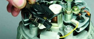
- The protective cover is dismantled. Using a screwdriver or wrench, the brush assembly is loosened; it must be brought out.
- The wear of the brush elements is checked. If their length is less than 5 mm, then replacement is necessary.
- Checking the generator device using a multimeter is performed together with the battery.
- The negative cable from the current source is connected to the corresponding plate of the control device.
- The positive contact from the charging equipment or battery is connected to the same output on the relay connector.
- Then the multimeter is set to the operating range from 0 to 20 volts. The probes of the device are connected to the brushes.
In the operating range of 12.8 to 14.5 volts, there should be voltage between the brush elements. If the parameter increases by more than 14.5 V, then the tester needle should drop to zero.
When diagnosing the built-in generator voltage relay-regulator, it is permissible to use a test light. The lighting source must turn on at a certain voltage interval and go out if this parameter increases above the required value.
The cable that controls the tachometer must be tested using a tester. On diesel cars this conductor is designated W. The resistance level of the wire should be approximately 10 ohms. If this parameter drops, this indicates that the conductor is broken and requires replacement.
Remote
The diagnostic method for this type of device is carried out similarly. The only difference is that the relay regulator does not need to be removed and removed from the generator unit housing. You can diagnose the device with the power unit running, changing the crankshaft speed from low to medium to high. When their number increases, it is necessary to activate the optics, in particular, the high beams, as well as the radio, stove and other consumers.
The AvtotechLife channel talked about self-diagnosis of the regulatory device, as well as the features of performing this task.
Basic automatic control processes
It doesn't matter what type of generator set is used in the car. In any case, it has a regulator in its design. The automatic voltage regulation system allows you to maintain a certain parameter value, regardless of the frequency at which the generator rotor rotates. The figure shows the generator voltage regulator relay, its diagram and appearance.
By analyzing the physics by which a generator set operates, it can be concluded that the output voltage increases as the rotor speed becomes higher. It can also be concluded that voltage regulation is carried out by reducing the current supplied to the rotor winding as the rotation speed increases.
Independent connection of the relay regulator to the generator’s on-board network (step-by-step instructions)
When installing a new control device, the following points must be taken into account:
- Before performing the task, it is necessary to diagnose the integrity and reliability of the contacts. This is a cable that runs from the vehicle body to the generator set housing.
- Then connect terminal B of the regulatory element to the positive contact of the generating set.
- It is not recommended to use twisted wires when making connections. They overheat and become unusable after a year of use. Soldering should be used.
- It is recommended to replace the standard conductor with a wire whose cross-section is at least 6 mm2. Especially if, instead of the factory generator, a new one is installed, which is designed to operate under current conditions above 60 A.
- The presence of an ammeter in the generator-battery circuit allows you to determine the power of power sources at a specific time.
Remote controller connection diagram
Connection diagram for remote type devices
This device is installed after the wire into which it will be connected is determined:
- In older versions of Gazelles and RAF, mechanisms 13.3702 are used. They are made in a metal or polymer case and are equipped with two contact elements and brushes. It is recommended to connect them to the negative open circuit; the outputs are usually marked. The positive contact is taken from the ignition coil. And the output of the relay is connected to the free contact on the brushes.
- VAZ cars use devices 121.3702 in a black or white case; there are also double modifications. In the latter, if one of the parts breaks down, the second regulator will remain working, but you need to switch to it. The device is installed in the open circuit of the positive circuit with terminal 15 to the contact of the B-VK coil. The conductor number 67 is connected to the brushes.
In newer versions of the VAZ, the relays are installed in the brush mechanism and connected to the ignition switch. If the car owner replaces the standard unit with an AC unit, then the connection must be made taking into account the nuances.
More details about them:
- The need to fix the unit to the vehicle body is determined by the car owner independently.
- Instead of a positive output, contact B or B+ is used here. It must be connected to the car's electrical network via an ammeter.
- Remote type devices are usually not used in such cars, and built-in regulators are already integrated into the brush mechanism. There is one cable coming from it, designated D or D+. It must connect to the ignition switch.
In cars with diesel engines, the generator unit can be equipped with output W - it is connected to the tachometer. This contact can be ignored if the unit is installed on a gasoline modification of the car.
User Nikolay Purtov spoke in detail about installing and connecting remote devices to a car.
Checking the connection
The engine must start. And the voltage level in the car’s electrical network will be controlled depending on the number of revolutions.
Perhaps, after installing and connecting a new generator device, the car owner will encounter difficulties:
- when the power unit is activated, the generator unit starts, the voltage value is measured at any speed;
- and after the ignition is turned off, the vehicle engine runs and does not turn off.
The problem can be solved by disconnecting the excitation cable, only then will the engine stop.
The engine may stall when the clutch is released and the brake pedal is pressed. The cause of the malfunction is residual magnetization, as well as constant self-excitation of the unit winding.
To avoid this problem in the future, you can add a light source to the gap in the exciting cable:
- the light will light when the generator is turned off;
- when the unit starts, the indicator goes out;
- the amount of current that passes through the light source will not be sufficient to excite the winding.
The Altevaa TV channel talked about checking the connection of the regulatory device after connecting the motorcycle to a 6-volt network.
Precautionary measures
The operation of a generator set requires compliance with certain rules, mainly related to the presence of electronic elements in them.
- The generator set must not be operated with the battery disconnected.
Even a short-term disconnection of the battery while the generator is running can lead to failure of the voltage regulator elements. If the battery is completely discharged, it is impossible to start the car, even if you tow it: the battery does not provide excitation current, and the voltage in the on-board network remains close to zero. It helps to install a properly charged battery, which is then replaced with the old, discharged one while the engine is running. To avoid failure of the voltage regulator elements (and connected consumers) due to increased voltage, it is necessary to turn on powerful electrical consumers, such as heated rear windows or headlights, while the batteries are being replaced. In the future, after half an hour or an hour of engine operation at 1500-2000 rpm, the discharged battery (if it is in good condition) will be charged enough to start the engine. - It is not allowed to connect electrical sources of reverse polarity (plus to ground) to the on-board network, which can happen, for example, when starting the engine from an external battery.
- Any checks in the generator set circuit with the connection of high voltage sources (above 14 V) are not allowed.
- When carrying out electric welding work on a car, the ground terminal of the welding machine must be connected to the part being welded. The wires going to the generator and voltage regulator should be disconnected.
Generator Maintenance
Maintenance of the generator set is kept to a minimum and does not require any special knowledge or skills; this work can be performed by every car enthusiast. Start servicing the generator by cleaning the external surfaces. Check the fastening of the generator to the engine, the reliability of the connection of the wires to the generator and voltage regulator, as well as the tension of the fan drive belt. If the tension is weak, then the generator operates unstable; if it is strong, the belt and bearings wear out quickly. Also check the condition of the drive belt. There should be no cracks or delaminations on it. The condition of the bearings can be checked by rotating the generator rotor by hand with the drive belt removed. When the bearings are in normal condition, the shaft rotation should occur smoothly, without jamming, strong play, noise or clicks. In principle, this work can be limited to until any malfunctions appear.
Control check
Before leaving, it is recommended to check the functionality of the generator set using the warning lamp installed on the instrument panel. After turning on the ignition and before starting the engine, the warning lamp lights up, which allows you to check its functionality. During normal operation of the generator set, the warning lamp goes out after the engine starts. For a normally operating generator set, at average engine speeds, the voltage should be in the range of 13.5...14.2 V. The magnitude of this voltage is measured with a voltmeter at the battery terminals.
Pre-repair diagnostics
A flashing battery charging indicator lamp does not always indicate a malfunction inside the generator. Often the malfunction is trivial and lies on the surface. Therefore, you should not immediately go into the generator and change the relay-regulator headlong, maybe it will help. Look at the preliminary diagnostic diagram. To carry it out, you may need a voltmeter with a scale of at least 15 V. Anyone can do these checks and thereby protect themselves from unnecessary, incorrect actions and loss of precious time.
If preliminary diagnostics have shown that the excitation winding circuit is working properly, and the fault is in the generator, then after removing it, it is advisable to check all the circuits, including the relay regulator, according to the diagrams described in the section
Removing and installing the generator
- Disconnect the negative wire from the battery terminal (key 10).
- Remove the plastic strap clamps from the air intake pipe and the starter and alternator wiring harness.
- Disconnect the generator field winding connector.
- Unscrew the nut from the 30th terminal of the generator (10 wrench).
- Unscrew the nut securing the generator to the tension bar (17 wrench).
- Using a mounting paddle, move the generator to the engine and remove the drive belt.
- Unscrew the three crankcase protection bolts (head 13) and remove it.
- Remove the right engine splash guard by unscrewing the five self-tapping screws with a 8mm socket head.
- Unscrew the nut 19 from the lower bolt securing the generator to the bracket.
- Remove the generator along with the air intake pipe. To do this, you need to tilt it slightly so that it goes down between the side member and the lower bracket for mounting the generator.
- Install the generator in reverse order.
Disassembling and replacing the voltage regulator
Begin your preparation by cleaning the outside surfaces of the generator.
- Remove the back cover along with the air intake pipe.
- Disconnect the wire from the relay regulator, unscrew the two M4 screws and remove the relay regulator. To remove the old-style relay-regulator, unscrew the wire secured under the extension terminal “30” of the generator. Insert the blade of a screwdriver between the relay-regulator housing and the brush holder. Using a screwdriver as a lever, pull out the relay regulator and pull out the brushes.
- Blow dust and dirt out of the internal cavity of the generator with compressed air using a compressor or pump.
- If the rotor contact rings are severely burned or worn, clean them with fine sandpaper.
- Install the new relay-regulator in the reverse order of removal.
If, after checking, the old relay-regulator turns out to be in working order (the test method is described in the next section), then:
- Clean the contact connections of the generator and relay-regulator from dirt and oil with a rag soaked in gasoline or solvent. Oil and dirt increase resistance at the contact points, which reduces the current delivered by the generator and increases wear on the brushes.
- check the minimum permissible protrusion of the brushes from the brush holder - 5 mm. If the brushes are stuck in the brush holder, replace the relay-regulator assembly. (For old-style relay regulators, it is enough to replace only the brush assembly.)
- put it in place.
Troubleshooting generator set components and parts
To find faults in the electrical circuits of the generator set, it is enough to have an ohmmeter. A more accurate check of winding units requires the use of special devices, such as PDO-1, which is used to search for faults in the windings by comparing their parameters. To check the relay regulator, you will need DC voltage sources of 12...14 V and 16...22 V. It is more convenient to carry out all tests on a generator removed from the car.
Checking the voltage regulator
Voltage regulators are not repaired, but replaced with new ones. However, before replacing it, it is necessary to establish exactly what it is that has failed.
Check on the car
To check, you must have a DC voltmeter with a scale of up to 15...30 volts. With the engine running at medium speed and the headlights on, measure the voltage at the battery terminals. It should be within the range of 13.5...14.2 V. If there is a systematic undercharging or overcharging of the battery and the regulated voltage does not fall within the specified limits, it is possible that the voltage regulator is faulty and needs to be replaced. In order to find out whether the regulator is working or not, we will check it according to the figure shown below.
Checking the removed regulator
The regulator removed from the generator is checked according to the following diagrams (old model on the left, new model on the right):
It is better to check the relay-regulator assembled with the brush holder, since in this case you can immediately detect breaks in the brush leads and poor contact between the terminals of the voltage regulator and the brush holder. Between the brushes, turn on a 1...3 W, 12 V lamp. To terminals “B”, “C” and to the regulator ground, connect a power source first with a voltage of 12...14 V, and then with a voltage of 16...22 V. If the regulator is working properly, then in the first In the second case, the lamp should be on, and in the second case, it should go out. If the lamp lights up in both cases, then there is a breakdown in the regulator, and if it doesn’t light up in both cases, then there is a break in the regulator or there is no contact between the brushes and the terminals of the voltage regulator.
Checking the rotor winding (excitation)
To check the winding, turn on the ohmmeter to measure resistance and bring its leads to the rotor rings. A working rotor should have a winding resistance in the range of 1.8...5 Ohms. If the ohmmeter shows an infinitely high resistance, this means that the field winding circuit is open. The rupture most often occurs at the place where the winding leads are soldered to the rings. You should carefully check the quality of this soldering. The check can be carried out with a needle, moving the winding leads at the place where they are soldered. The combustion of the winding is indicated by darkening and shedding of its insulation, which can be detected visually. The combustion of the windings leads to a break or an interturn short circuit in the winding with a decrease in its total resistance. A partial interturn short circuit, in which the winding resistance changes little, can be detected with the PDO-1 device by comparing this winding with a known good one. After checking the winding resistance, you should check that it does not have a short to ground. To do this, one ohmmeter lead is brought to any rotor ring, and the other to its beak. For a working winding, the ohmmeter will show an infinitely high resistance. A faulty rotor must be replaced.
Checking the stator winding
The stator is checked separately, after disassembling the generator. The terminals of its winding must be disconnected from the rectifier valves.
First of all, check with an ohmmeter whether there are any breaks in the stator winding (a). Then, by connecting the ends of the ohmmeter to one of the winding terminals and the non-insulated section of the stator iron, check whether its turns are shorted to ground (b). The ohmmeter should show an open circuit in a working winding. Checking the turn-to-turn short circuit in the stator windings can be carried out with sufficient accuracy using the PDO-1 device. The break can also be checked with an ohmmeter by connecting it to the zero point and alternately to the output of each phase. An external inspection should make sure that there is no cracking of the insulation and no burning of the winding, which occurs when there is a short circuit in the valves of the rectifier unit. Replace the stator with such damaged winding.
Checking the valves (diodes) of the rectifier unit
The diodes of the rectifier unit are checked after disconnecting it from the stator winding with an ohmmeter. A working valve allows current to flow in only one direction. Faulty - may either not pass current at all (open circuit), or pass current in both directions (short circuit). If one of the rectifier valves is damaged, the entire rectifier unit must be replaced. A short circuit in the valves of the rectifier unit can be checked without disassembling the generator, but only by removing the protective casing. Also, terminal “B” of the regulator is disconnected from terminal “30” of the generator and the wire from terminal “B” of the voltage regulator. You can check with an ohmmeter or using a lamp (1...5 W, 12 V) and a battery. In order to simplify the fastening of rectifier parts, three valves (with a red mark) create a “plus” of rectified voltage on the housing. These valves are “positive” and they are pressed into one plate of the rectifier block, connected to terminal “30” of the generator. The other three valves (“negative” with a black mark) have a “minus” rectified voltage on the body. They are pressed into another plate of the rectifier unit, connected to ground. First, check if there is a short circuit in the “positive” and “negative” valves at the same time. To do this, connect the “plus” of the battery through the lamp to terminal “30” of the generator, and the “minus” to the generator body:
If the lamp is on, then the “negative” and “positive” valves have a short circuit. A short circuit of the “negative” valves can be checked by connecting the “plus” of the battery through a lamp to one of the mounting bolts of the rectifier unit, and the “minus” to the generator housing:
The lamp burning means a short circuit in one or more “negative” valves. It should be remembered that in this case, the burning of the lamp may also be a consequence of the short circuit of the turns of the stator winding to the generator housing. However, such a malfunction is less common than valve short circuits. To check for a short circuit in the “positive” valves, connect the “plus” valves of the battery through a lamp to terminal 30 of the generator, and the “minus” valve to one of the bolts securing the rectifier unit:
The lamp will indicate a short circuit in one or more “positive” valves. A break in the valves without disassembling the generator can be detected either with an oscilloscope or when checking the generator on a bench by a significant decrease (20-30%) in the amount of current supplied compared to the rated one. If the windings, additional diodes and the generator voltage regulator are working properly, and there is no short circuit in the valves, then the reason for the decrease in the output current is a break in the valves.
Checking additional diodes
The short circuit of additional diodes can be checked using the following diagram:
Connect the “plus” of the battery through a lamp (1...3 W, 12 V) to terminal “61” of the generator, and the “minus” to one of the mounting bolts of the rectifier unit. If the lamp lights up, then there is a short circuit in one of the additional diodes. You can find a damaged diode only by removing the rectifier unit and checking each diode individually. A break in additional diodes can be detected with an oscilloscope by the distortion of the voltage curve on plug “61”, as well as by low voltage (below 14 V) on plug “61” at an average rotation speed of the generator rotor.
Capacitor check
The capacitor serves to protect the vehicle's electronic equipment from voltage surges in the ignition system, as well as to reduce interference with radio reception. Damage to the capacitor or loosening of its mounting on the generator (deterioration of contact with ground) is detected by an increase in interference to radio reception when the engine is running. Approximately the serviceability of the capacitor can be checked with a megger or tester (on a scale of 1...10 MOhm). If there is no break in the capacitor, then at the moment the probes of the device are connected to the terminals of the capacitor, the arrow should deviate in the direction of decreasing resistance, and then gradually return back. The capacitance of the capacitor, measured with a special device, should be 2.2 μF + 20%.
Checking and replacing bearings
Start checking the bearings with an external inspection, identifying cracks in the races, enveloping or chipping of metal, the presence of corrosion, etc. Check for ease of rotation and the absence of strong play and noise. If the bearing seats are heavily worn or damaged, it must be replaced. Procedure for replacing bearings (generator removed from vehicle).
- Remove the rear cover along with the air intake pipe.
- Remove the voltage regulator.
- Unscrew the generator pulley and remove the key.
- Unscrew the 4 nuts of the coupling bolts and remove the front cover of the generator along with the rotor and bearings.
- Remove the defective bearing from the drive side cover. Unscrew the nuts of the screws tightening the bearing mounting washers, remove the washers with screws and press out the bearing using a hand press. If the screw nuts do not come off (the ends of the screws are open), cut off the ends of the screws.
- Press in the new bearing. To do this, place the new bearing on the seat, and the old one on top of it. Lightly tap the old bearing with a hammer to force the new bearing into its seat. If the bearing has too much interference, spray the outer ring with WD-40.
- Using a puller, press the second bearing from the back of the rotor.
- Press in a new bearing (see point 6).
- Reassemble in reverse order.
Checking the covers
An external inspection determines the absence of cracks passing through the bearing seat, broken legs of the generator mounting, and severe damage to the seats. If such damage is present, the cover must be replaced. If severe wear of the bearing seats is detected, replace the caps.
Tips for increasing the service life of the relay regulator
To prevent rapid failure of the regulatory device, you must adhere to several rules:
- Do not allow the generator set to become heavily contaminated. From time to time you should perform a visual diagnosis of the device's condition. In case of serious contamination, the unit is removed and cleaned.
- The tension of the drive belt should be checked periodically. If necessary, it is stretched.
- It is recommended to monitor the condition of the generator set windings. They should not be allowed to darken.
- It is necessary to check the quality of contact on the control cable of the regulatory mechanism. Oxidation is not allowed. When they appear, the conductor is cleaned.
- Periodically, you should diagnose the voltage level in the electrical network of the car with the engine running and switched off.
Functionality check
The operating condition of the device can be determined by inspecting the brushes, the length of which must be at least 5 mm. And diagnosing the state of the regulator is carried out by using a constant voltage source on which the initial parameter can be changed. For these purposes, it is enough to have a battery, a couple of AA batteries and a regular 12-volt incandescent lamp or voltmeter.
First you need to connect the “+” from the power supply to the corresponding connector of the relay regulator, and the “-” to the common plate of the device. Next, a lamp or voltmeter is connected to the brushes, which are supplied with a voltage of 12 volts at this time. It is important to understand that when more than 15 Volts are supplied to the regulator, there will be no voltage between the brushes. This is what indicates the working condition of the device. The unit will be diagnosed as faulty in cases where the control lamp does not light up or lights up at any voltage value.
Is it possible to make a regulator with your own hands?
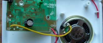
An example is considered on the regulatory mechanism for a scooter. The main nuance is that for correct operation the generator unit will need to be disassembled. A separate conductor must lead out the ground cable. The device is assembled according to the circuit of a single-phase generator.
Algorithm of actions:
- The generating set is disassembled and the stator element is removed from the scooter motor.
- There is ground around the windings on the left; it needs to be desoldered.
- Instead, a separate cable for winding is soldered. Then this contact is brought out. This conductor will be one end of the winding.
- The generator device is being reassembled. These manipulations are carried out so that two cables come out of the unit. They will be used.
- Then a shunt device is connected to the resulting contacts. At the final stage, the yellow cable from the old relay is connected to the positive terminal of the battery.
Basic Concepts
The relay regulator, which is an important part of the on-board electrical network, is responsible for regulating the current generated by the vehicle generator. Due to the operation of the relay, the battery is prevented from overcharging, which is detrimental to it. Those knowledgeable in electrical engineering, cars and motorcycle enthusiasts will notice: according to the description, this is a regular voltage stabilizer! Essentially, that's what he is. But let's understand a little about generators.
In essence, both direct and alternating current generators are electrical machines that convert mechanical energy into electric current. Today, alternators are more common because they do not use current-collecting brushes, which tend to burn or become severely deformed as the device is used. The output voltage of both types of generators depends on the speed at which the magnetic field rotates inside it and on the magnetic force. The so-called excitation winding is initially supplied to excitation current , due to which magnetic induction is induced. The strength of this current must be adjusted. At a certain point, power needs to stop being supplied to the field winding - another point that needs to be monitored. Further, since in alternating current generators the position of the poles “ + ” and “ - ” is constantly changing, the current must be rectified. The diode bridge is responsible for this, but the range of output voltages can be quite wide. And now we can highlight the main tasks of the generator relay regulator:
- Maintain a voltage range ( 13.5 – 14.5 Volts ) in the network of a car or motorcycle, as well as at the terminals of their battery;
- Excitation current adjustment;
- Stopping the power supply from the battery to the field winding.
Essentially, the generator relay “monitors” the output voltage and current that powers the voltage winding. As soon as the output voltage becomes too high, the relay reduces the excitation current. If the situation is reverse and the generator voltage has decreased, the current to the exciting winding should increase. This happens many times, and stabilization lasts a fraction of a second . Thus, the relay ensures the normal operation of the generator, which now provides the optimal voltage for electrical receivers (radio tape recorders, for example), and saves the life of the battery, also preventing its failure due to recharging with too much current.