If for an ordinary person the perception of information occurs by reading words and letters, then for mechanics and installers they are replaced by alphabetic, digital or graphic symbols. The difficulty is that while the electrician completes his training, gets a job, and learns something in practice, new SNiPs and GOSTs appear, according to which adjustments are made. Therefore, you should not try to learn all the documentation at once. It is enough to gain basic knowledge and add relevant data as you work.
Basic standards and regulations
The large volume of regulations causes difficulties even for experienced specialists. To correctly study project documentation, you should familiarize yourself with the basic principles of creating diagrams and symbols. You can clarify individual details using the information provided in the primary sources:
| GOST number | Information | |
| 2.701-2008; 2.702-2011 | Types of schemes, general requirements, definitions | |
| 2.709-89 | UGO | Wires |
| 2.755-87 | Contactors, switches, other switching devices | |
| 2.721-74 | Products for secondary circuits | |
Dimensions of elements in the diagrams
The resistor is designated by a 10x4 mm rectangle.
In the UGO potentiometer, the length is increased to 20 mm to simplify the designation of the moving structural element.
The following GOSTs provide regulatory requirements for images of other components:
- 2.728-74 - fuses, rheostats;
- 2.255-74 - switches;
- 2.736-68 - piezoelements, transformers;
- 2.743-91 - microcircuits;
- 2.756-73 - relays, coils;
- 2.732-68 - incandescent lighting and signal lamps;
- 2.730-73 - zener diodes, diodes.
In addition to dimensions, standards have been established for the angle of inclination of oblique lines in the designations of transistors and other semiconductor devices.
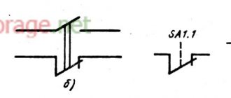
Limit switch
Limit switches are used to make or break a circuit.
Limit switch
They are installed on special mechanisms so that they do not move during operation. They are depicted on the diagram as horizontal lines with a parallel stick and are the beginning of any chain or diagram.
Important! These devices are divided into mechanical and contactless. The former are more in demand on the market, and they can be found among household equipment, electrical appliances or cars.
Non-contact - used in those mechanisms where contact with moving parts is impossible.
Limit switches can also be inductive or capacitive.
Designation of electrical elements on diagrams
Some experts, after carefully looking at the diagram, can say what it is and how it works. Some can even immediately indicate possible problems that may arise during operation. It’s simple - they know the circuit design and element base well, and are also well versed in the symbols of circuit elements. This skill takes years to develop, but for dummies, it’s important to remember the most common ones first.
Designation of LED, Zener diode, transistor (various types)
Electrical panels, cabinets, boxes
On the power supply diagrams of a house or apartment there will definitely be a designation of an electrical panel or cabinet. In apartments, the terminal device is mainly installed there, since the wiring does not go further. Houses can be designed to install an electrical branch cabinet - if there is a route from it to illuminate other buildings located at some distance from the house - a bathhouse, a summer kitchen, a guest house. These other symbols are in the next picture.
Designation of electrical elements on diagrams: cabinets, panels, consoles
If we talk about images of the “filling” of electrical panels, it is also standardized. There are symbols for RCDs, circuit breakers, buttons, current and voltage transformers and some other elements. They are shown in the following table (the table has two pages, scroll by clicking on the word “Next”)
| Number | Name | Image on the diagram |
| 1 | Circuit breaker (automatic) | |
| 2 | Switch (load switch) | |
| 3 | Thermal relay (overheat protection) | |
| 4 | RCD (residual current device) | |
| 5 | Differential automatic (difavtomat) | |
| 6 | Fuse | |
| 7 | Switch (switch) with fuse | |
| 8 | Circuit breaker with built-in thermal relay (for motor protection) | |
| 9 | Current transformer | |
| 10 | Voltage transformer | |
| 11 | Electricity meter | |
| 12 | A frequency converter | |
| 13 | Button with automatic opening of contacts after pressing | |
| 14 | Button with contact opening when pressed again | |
| 15 | A button with a special switch to turn off (stop, for example) |
Element base for electrical wiring diagrams
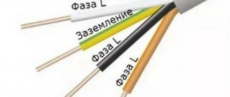
When drawing up or reading a diagram, the designations of wires, terminals, grounding, zero, etc. are also useful. This is what a novice electrician simply needs, or in order to understand what is shown in the drawing and in what sequence its elements are connected.
| Number | Name | Designation of electrical elements on diagrams |
| 1 | Phase conductor | |
| 2 | Neutral (zero working) N | |
| 3 | Protective conductor (“ground”) PE | |
| 4 | Combined protective and neutral conductors PEN | |
| 5 | Electrical communication line, buses | |
| 6 | Bus (if it needs to be allocated) | |
| 7 | Busbar taps (made by soldering) |
An example of the use of the above graphic images is in the following diagram. Thanks to the letter designations, everything is clear even without graphics, but duplication of information in diagrams has never been superfluous.
An example of a power supply diagram and a graphic representation of the wires on it
Picture of sockets
The wiring diagram should indicate the installation locations of sockets and switches. There are many types of sockets - 220 V, 380 V, hidden and open installation types, with a different number of “seats”, waterproof, etc. To give a designation for each is too long and unnecessary. It is important to remember how the main groups are depicted, and the number of contact groups is determined by the strokes.
Designation of sockets in the drawings
Sockets for a single-phase 220 V network are indicated on the diagrams in the form of a semicircle with one or more segments sticking up. The number of segments is the number of sockets on one body (illustration in the photo below). If only one plug can be plugged into the socket, one segment is drawn upward, if two, two, etc.
Symbols for sockets in electrical diagrams
If you look at the images closely, notice that the symbolic image that is on the right does not have a horizontal line that separates the two parts of the icon. This line indicates that the socket is concealed, that is, it is necessary to make a hole in the wall for it, install a socket box, etc. The option on the right is for open mounting. A non-conductive substrate is attached to the wall, and the socket itself is on it.
Also note that the bottom of the left diagram has a vertical line through it. This indicates the presence of a protective contact to which grounding is connected. Installing sockets with grounding is mandatory when turning on complex household appliances such as a washing machine, dishwasher, oven, etc.
Designation of a three-phase outlet in the drawings
The symbol of a three-phase outlet (380 V) cannot be confused with anything. The number of segments sticking up is equal to the number of conductors that are connected to this device - three phases, zero and ground. Total five.
It happens that the lower part of the image is painted black (dark). This means that the outlet is waterproof. These are placed outdoors, in rooms with high humidity (baths, swimming pools, etc.).
Switch Display
The schematic designation of switches looks like a small circle with one or more L- or T-shaped branches. Taps in the shape of the letter “G” indicate an open-mounted circuit breaker, while those in the shape of the letter “T” indicate a flush-mounted switch. The number of taps displays the number of keys on this device.
Conventional graphic symbols of switches on electrical diagrams
In addition to the usual ones, there may be pass-through switches - to be able to turn on/off one light source from several points. Two letters “G” are added to the same small circle on opposite sides. This is how a single-key pass-through switch is designated.
What does a schematic representation of pass-through switches look like?
Unlike conventional switches, when using two-key models, another bar is added parallel to the top one.
Lamps and fixtures
Lamps have their own designations. Moreover, there is a difference between fluorescent lamps and incandescent lamps. The diagrams even show the shape and dimensions of the lamps. In this case, you just need to remember what each type of lamp looks like on the diagram.
Image of lamps on diagrams and drawings
Basic UGO for single-line diagrams of electrical panels
| UGO | Name |
| Thermal relay | |
| Contactor contact | |
| Switch - load switch | |
| Automatic - circuit breaker | |
| Fuse | |
| Differential circuit breaker | |
| RCD | |
| Voltage transformer | |
| Current transformer | |
| Switch (load switch) with fuse | |
| Motor protection circuit breaker (with built-in thermal relay) | |
| A frequency converter | |
| Electricity meter | |
| Normally closed contact with reset button or other push-button switch, with reset and opening by means of a special actuator of the control element | |
| Normally closed contact with push-button switch, with reset and opening by retracting the control button | |
| Normally closed contact with push-button switch, reset and open by pressing the control button again | |
| Normally closed contact with push-button switch, with automatic reset and opening of the control element | |
| Delayed closing contact that initiates upon return and operation | |
| Delayed closing contact which only operates on return | |
| Delayed closing contact which is only initiated when triggered | |
| Delayed closing contact which is actuated by return and tripping | |
| Delayed closing contact which only operates on return | |
| Delayed closing contact that only switches when triggered | |
| Timing relay coil | |
| Photo relay coil | |
| Pulse relay coil | |
| General designation of a relay coil or contactor coil | |
| Indication lamp (light), lighting | |
| Motor drive | |
| Terminal (separable connection) | |
| Varistor, surge arrester (surge suppressor) | |
| Arrester | |
Socket (plug connection):
| |
| A heating element |
Varieties and types of electrical circuits
According to the GOST 2.702-2011 standard, documents of this type must contain symbols of the components of a product that operates using electricity. To solve typical problems, a home handyman only needs to study 3 types of diagrams:
- functional;
- principled;
- editing room
“Structural” and other modifications of drawings are used in a set of documentation for large objects.
Functional
This type of diagram is used to explain the principles of operation of the system. The functional element is marked with a large rectangle. The purpose of the block is written inside: control, coordination, etc. The arrows of inputs and outputs are supplemented with explanations about power circuits and peripheral equipment.
Fundamental
In this drawing, individual elements, devices, and mutual connections are indicated by graphic symbols. When designing power lines, you can use a relatively simple single-line diagram. Fundamental - used to develop complex systems containing different types of circuits and devices.
Assembly
This document simplifies installation work. The diagram indicates not only the types of components, but also the distances between them. Information about chain lengths can be used to purchase cable products. Special marks indicate fastening features, ratings, and sequence of work operations.
Lighting
Light in an apartment, non-residential premises, at the entrance, on the street or in an electrical panel room can be connected both in groups and individually. One lighting lamp is designated as a circle with a cross inside and a vertical line.
Different types of lighting
The line for emergency lighting is indicated by a long dotted line. The lighting groups in the diagram can be seen in the form of a rectangle with a completely shaded area inside.
For all living spaces, it is recommended to install separate lighting groups for the kitchen, bath or bedroom. This will reduce the load, as a result the voltage will not change sharply.
You might be interested in WAGO connectors
Attention! Also, if there are many devices connected to the network, it is recommended to use a stabilizer.
Graphic images
To create a drawing, symbols of circuit elements and conductive lines are used. Additional inscriptions are used to indicate the resistance of the resistor or another value.
To avoid errors, you should carefully study individual symbols.
Lines
A straight line denotes a conductor. Above this element there is an inscription clarifying important characteristics:
- core material;
- voltage;
- strength and type of current.
The junction is indicated by a bold dot. If there is no such element at the intersection, then there is no electrical connection.
Tires and wires
To make it easier to read the diagrams in the drawing, instead of written explanations, special graphics are used:
- slanted notches - number of conductors;
- dotted line with different (identical) lengths of segments - grounding line (emergency lighting);
- inverted letter "P" - tray;
- arrow up from the bold dot - vertical laying with cable transition to a higher level.
Such designations help to use free space economically. The examples explain the possibility of visually presenting the data necessary for the correct execution of individual installation operations.
Panels, cabinets and boxes
The dimensions of UGO boxes and other large functional components are established according to the actual dimensions of the products in the scale of the created drawing. It is acceptable to enlarge these elements if it is necessary to show a detailed diagram of suitable wiring.
Different UGOs indicate the corresponding type of product:
| Component | Varieties |
| Box | Input, branch, traction, equipped with clamps |
| Shield | Main, group, laboratory, emergency lighting |
| Closet | Single and double-sided service, open |
Sockets, switches and switches
The designations of products in this category are divided into groups according to the installation method and level of protection. From the picture you can determine:
- ranges IP20... 23 and IP44... 55;
- number of keys, poles;
- hidden or open installation option;
- pass-through type of switch;
- presence (absence) of zero position, grounding.
The vertical line indicates the number of sockets (switches) in one block.
Junction box
This device has a cover, usually round, on the sides of which there are technological holes necessary for inserting electrical cables of various sections and securing the cable channel. A box is used to lay and mask the joints of wires, ensuring the correct placement of electrical energy in the room. Indicated as a large letter T enclosed in a circle.
Letter designation
Switches on a single line diagram
Switches for turning on or off appliances are mainly depicted as vertical lines with different dots and asterisks at the end. If the switch has a fuse, then a small square is added to the line. The main designations of switches can be read in GOST 2.755 of 1987.
Conventional graphic symbols on electrical circuits
Due to the fact that at the moment there are a huge number of various elements of electrical circuits, each of them needs its own designation in the form of symbols, letters and numbers, as well as graphic images. To avoid disagreements and discrepancies, regulatory documents have been developed that unambiguously assign alphanumeric and graphic designations to each element. The following list includes all the major convention standards:
- GOST 2.710 81 - State standard requirements for alphanumeric designations of various structural electrical elements and electrical appliances;
- GOST 2.747 68 - Requirements for the dimensional characteristics of graphic images;
- GOST 21.614 88 - Standards adopted for planning the installation of electrical equipment and wiring;
- GOST 2.755 87 - Requirements for the designation of contacts, connections and switching equipment on the diagram;
- GOST 2.709 89 - Standard regulating the designation of contact and wiring connections;
- GOST 21.404 85 - Requirements for the designation of automation equipment when describing technical processes at an enterprise.
Drawings of vacuum devices
Before moving on to the designations of circuit elements, it should be said that the circuits themselves have a letter designation. Thus, block diagrams are designated by the number 1, functional diagrams - 2, schematic (complete) diagrams - 3, wiring diagrams (connection diagrams) - 4, connection diagrams - 5, general diagrams - 6, layout diagrams - 7, and integration diagrams - 0 .
Gas generator drawing
By type of designation there are also:
- electrical diagrams - E;
- hydraulic circuits - G;
- pneumatic circuits - P;
- gas circuits - X;
- kinematic diagrams - K;
- vacuum circuits - B;
- optical circuits - L;
- energy schemes - P;
- division schemes - E;
- combined schemes - S.
You might be interested Star-delta starterOptical circuit of theodolite
All types of graphic documents have their own designations, which are regulated by special state standards and other regulatory documents. For example, you can give basic graphic symbols for some types of electrical circuits. Functional diagrams often indicate the main components and automation equipment.
Functional UGO table
According to the picture, the designations are as follows:
- A - Devices that are installed behind an electrical panel or distribution box. 1 - main type, 2 - allowed;
- B - Devices that are installed within the electrical panel or distribution box;
- C - Graphic representation of actuators;
- D - The method of influence of the actuator on the organ that regulates it in the event of a power failure to the element. The first option is the opening of the regulatory body, the second is its closure, and the third is no change;
- E - Actuator with installed manual drive. This type of mechanism can also be specified in any case from the previous item in the list;
- F - Image of communication lines: 1 - common line, 2 - intersection line without connection, 3 - line with connections.
There are several types of symbols in single-line and complete diagrams. Below are the most common ones.
UGO table for power supplies
This image shows the following types of power supplies:
- A - sources of direct current and voltage. Their polarity is determined by the “+” and “-” signs on different sides;
- B - alternating voltage;
- C is the alternating and direct voltage used in the device, which can operate on all types of electricity;
- D — Battery or galvanic power source;
- E - Schematic representation of a battery or accumulator, which consists of several batteries.
UGO electromechanical devices
Designations of electromechanical elements and devices include:
- A - Coils of electrical devices, which include relays, magnetic starters, and so on;
- B - graphic symbols for the receiving parts of thermal elements;
- C - Device coil with mechanical lock;
- D - Contact elements of switching devices, including making, breaking and switching types;
- E - UGO for switches and buttons;
- F - Designation of the switch.
Terminal box
When installing wiring in a living room, the wires are branched inside. Each room has individual wiring to which various devices are connected. In nodal areas, instead of twists and insulation, a terminal box is used. These devices provide fire protection measures in the room, the risk of short circuit or fire is minimized.
Designation of ASU on the diagram
The terminal block can be installed only if the cores are connected correctly and the wires required for the density of contacts are obtained. The terminal box separates the connection point of the wires from the surface of the walls, and it also plays an aesthetic role.
According to the scope of application, the devices can be:
- External, which are connected from the street or entrance;
- Internal open type. Suspended from ceilings and walls;
- Internal closed type. They are used inside the walls of the room in grooves.
How the junction box is indicated on the diagram
The terminal box is depicted on the diagram as a square crossed out by a vertical line. Identified in bold.
Important! All these devices, depending on their purpose, use and design, may be labeled differently. This helps a person choose the right terminal box more competently. They can be used under water or in air, have protection from chemical influences, etc. All this can be found in the product labeling.
For example, a terminal box with fire protection is designated 1ExeIIT6.
Letter designations
In addition to graphic ones, there are also letter symbols. Without their use, a lot of inconsistencies may arise when reading diagrams and drawings. Like graphic, alphanumeric markings are regulated by GOST and regulatory documents. The list below shows the alphanumeric designation of the main elements of electrical circuits:
- Switches, controllers and switches - B;
- Electric generators and engines - G;
- Diodes - D;
- Buttons - Kn;
- Lamps - L;
- Electric motors of various types - M;
- Fuses - Pr;
- Rectifiers - Vp;
- Magnetic starters and contactors - K;
- Capacitors - C;
- Control buttons - Ku;
- Electromagnets - Um;
- Inductors - L;
- Relay - P;
- Resistors - R.
Designations of kinematic drawings
Introduction
But let's start a little from afar... Every young specialist who comes to design begins either by folding drawings, or by reading regulatory documentation, or by drawing “this” according to this example. In general, normative literature is studied in the course of work and design.
It is impossible to read all the normative literature related to your specialty or even a narrower specialization. Moreover, GOST, SNiP and other standards are periodically updated. And each designer has to monitor changes and new requirements of regulatory documents, changes in the lines of electrical equipment manufacturers, and constantly maintain their qualifications at the proper level.
Remember Lewis Carroll in Alice in Wonderland?
“You have to run as fast as you can just to stay in place, and to get somewhere, you have to run at least twice as fast!”
This is not my way of whining about “how hard the life of a designer is” or boasting “look, what an interesting job we have.” That's not what we're talking about now. Given such circumstances, designers adopt practical experience from more experienced colleagues; they simply know how to do many things correctly, but do not know why. They work according to the principle “That’s the way it is here.”
Sometimes these are quite basic things. You know how to do it right, but if they ask “Why is this?”, you won’t be able to answer right away, referring at least to the name of the regulatory document.
In this article, I decided to structure the information regarding symbols, sort everything out, and collect everything in one place.
Representation of electrical equipment on plans
According to GOST 21.210-2014, a document regulating conventional graphic images of electrical equipment and wiring on plans, there are clear symbols for each type of electrical devices and the links connecting them: wiring, buses, cables. They are distributed for each type of equipment and unambiguously define it on the diagram in the form of a graphic or alphanumeric symbol.
The document provides views for:
- Electrical equipment, electrical devices and electrical receivers;
- Wiring lines and conductors;
- Tires and busbars;
- Boxes, cabinets, panels and remote controls;
- Switches, switches;
- Plug sockets;
- Lamps and spotlights.
Electrical equipment, electrical devices and electrical receivers
The category of electrical equipment includes: power transformers, oil switches, disconnectors and separators, short circuiters, grounding switches, automatic high-speed switches and concrete reactors.
UGO table for electrical equipment
Electrical devices and receivers include: simple electrical devices, general electrical devices with motors, electrical devices operating on an electric drive, devices with generators, devices that are motors and generators, transformer devices, capacitor and complete units, storage equipment, electric heating elements. Their designations are shown in the picture below.
UGO for electrical devices
Wiring and conductor lines
This category includes: wiring lines, control circuits, voltage lines, grounding lines, wires and cables, as well as their possible types of wiring (in a tray, under the baseboard, vertical, in a box, etc.). The tables below provide the main designations for this category.
The first table of designations for wiring lines
Wiring lines are cables and wires capable of transmitting electricity over fairly long distances. Electrical devices that are capable of transmitting electricity over a short distance are most often called conductors. For example, from a current generator to a transformer and so on.
Second table of designations for wiring lines
Third table of designations for wiring lines
Fourth table of designations for wiring lines
Tires and busbars
Busbars are cable devices that consist of conductor elements, insulation and distributors that transmit and distribute electricity in industrial premises. The symbols of tires and busbars are presented in the picture below.
Designation of tires and busbars
Boxes, cabinets, panels and remote controls
Among the boxes we can distinguish branch, inlet, broach, clamp. There are laboratory switchboards, regular and emergency lighting, and automatic switches. All these elements are needed to distribute electricity between individual sections of the circuit and devices. The designation conditions for these elements are presented in the picture.
UGO panels and control panels
Switches, switches and sockets
This includes plug sockets.
First table of symbols for switches
All these elements are used to switch, turn on and off electrical circuits.
Second table of symbols for switches
This could be lighting or voltage changes. The following tables contain basic designations for this type of electrical elements.
Third table of symbols for switches
Lamps and spotlights
Many circuits contain lamps, spotlights and other lighting elements. They are needed not only to signal certain circuit states, but also to illuminate some cases.
UGO lamps
Monitoring and control devices
Such devices include meters, programmed devices, measuring instruments, pressure gauges, temperature controllers and time relays. Their main element is sensors sensitive to certain factors.
Symbols of control devices
They have the following designations.
Symbols of control devices continued
The article cannot contain the graphic and alphanumeric designations of all electrical devices and elements, but the most commonly used ones were discussed in detail. GOST documentation of schematic graphic designations of electrical elements on circuits of various types and types, as well as their decoding, was also described.
Circuit breakers and fuses
Circuit breakers or fuses are used to completely cut off power to all household appliances during a power surge, thereby preventing short circuits or failure of devices. In any room, residential or industrial, it is necessary to install several machines for different groups. These devices are depicted as vertical lines and dots.
Attention! Automatic machines are considered the main part of single-line diagrams in electrical engineering.
The machines are used mainly in private homes and industrial premises. They can be single-pole or three-pole. The former are easier to use and are necessary to protect individual sections of the chain. Single-pole circuit breakers warn against short circuits or overloads within the network.
Regulations
Taking into account the large number of electrical elements, a number of normative documents have been developed for their alphanumeric (hereinafter referred to as BO) and conventional graphic designations (UGO) to eliminate discrepancies. Below is a table showing the main standards.
Table 1. Standards for graphic designation of individual elements in installation and circuit diagrams.
| GOST number | Short description |
| 2.710 81 | This document contains GOST requirements for BO of various types of electrical elements, including electrical appliances. |
| 2.747 68 | Requirements for the dimensions of displaying elements in graphical form. |
| 21.614 88 | Accepted codes for electrical and wiring plans. |
| 2.755 87 | Display of switching devices and contact connections on diagrams |
| 2.756 76 | Standards for sensing parts of electromechanical equipment. |
| 2.709 89 | This standard regulates the standards in accordance with which contact connections and wires are indicated on diagrams. |
| 21.404 85 | Schematic symbols for equipment used in automation systems |
It should be taken into account that the element base changes over time, and accordingly changes are made to regulatory documents, although this process is more inert. Let's give a simple example: RCDs and automatic circuit breakers have been widely used in Russia for more than a decade, but there is still no single standard according to GOST 2.755-87 for these devices, unlike circuit breakers. It is quite possible that this issue will be resolved in the near future. To keep abreast of such innovations, professionals monitor changes in regulatory documents; amateurs do not have to do this; it is enough to know the decoding of the main symbols.
Load switch
The load switch, symbol, in the diagram looks almost exactly the same as the automatic one, with the only difference being that at the end there is not an asterisk, but a small circle. Such a device is used in distribution networks, transformer lines that operate at rated voltage, and with their help it is possible to turn on or off an additional load.
You may be interested in this Features of semiconductors
Main advantages of the device:
- Low price compared to other switches;
- Quick shutdown of the load on the network;
- Possibility of using inexpensive fusible circuit breakers for protection against power surges;
- Can function without an additional disconnector.
Types of electrical circuits
In accordance with ESKD standards, diagrams mean graphic documents on which, using accepted notations, the main elements or components of a structure, as well as the connections connecting them, are displayed. According to the accepted classification, there are ten types of circuits, of which three are most often used in electrical engineering:
- Functional, it shows the node elements (depicted as rectangles), as well as the communication lines connecting them. A characteristic feature of this scheme is minimal detail. To describe the main functions of nodes, the rectangles displaying them are signed with standard letter designations. These can be various parts of the product that differ in functionality, for example, an automatic dimmer with a photo relay as a sensor or a regular TV. An example of such a scheme is presented below.
Example of a functional diagram of a television receiver - Principled. This type of graphic document displays in detail both the elements used in the design and their connections and contacts. The electrical parameters of some elements can be displayed directly in the document, or presented separately in the form of a table.
Example of a circuit diagram of a milling machine
If the diagram shows only the power part of the installation, then it is called single-line; if all elements are shown, then it is called complete.
Single Line Diagram Example
- Electrical wiring diagrams. These documents use positional designations of elements, that is, their location on the board, method and order of installation are indicated.
Installation diagram of a stationary flammable gas detector
If the drawing shows the wiring of the apartment, then the locations of lighting fixtures, sockets and other equipment are indicated on the plan. Sometimes you can hear such a document called a power supply diagram; this is incorrect, since the latter shows how consumers are connected to a substation or other power source.
Having dealt with the electrical circuits, we can move on to the designations of the elements indicated on them.
Main types of switches
According to electrical engineering terminology, a switch refers to a device that allows electric current to flow through a circuit. Its distinctive feature is a unique system, the action of which is aimed at quickly breaking contact. All functions of the device are carried out by a manual drive, which reliably turns off the voltage during repair and maintenance work.
There are several types of switches, among which the following can be distinguished:
- Reversible (Fig. 1). With the help of these devices, voltage is transferred from one circuit to another. They are mainly used when there is a need to switch the current supply from the emergency section of the circuit to the working one. Special switch rooms are provided for installation of devices. This type of switches has high operational and technical indicators.
- Explosive (Fig. 2). Connects to common output circuits, ideal for private houses, apartments, office buildings. This device is used to connect an object to a common network. They are installed in the electrical panel with the switch lever leading outwards. There is a wide range of models on the market.
- Reversible (Fig. 3). They are used in three-phase electrical networks, ensuring their normal functioning. With the help of these devices, the load is distributed between the lines, and the current is uninterruptedly supplied to consumers. Installation of switches is carried out in a horizontal or vertical position, all switching is done manually. Certain types of devices can be controlled remotely.
The main part of the switch is the rotary contact system. The design of the moving contact is a knife or a spring-loaded fork, and the fixed contact is a knife or two plates, spring-loaded by means of a steel split ring. In addition, the switch is equipped with a handle or manual drive, contact terminals for connecting wires. A 1-way breaking switch with three poles is equipped with three input and three output contacts, and a 2-way changeover switch has six input and six output contacts. For each pole there are 1 or 2 arc chutes, according to the number of directions.
The design of the contact group does not allow the moving contact to spontaneously fall out under the influence of vibration or under its own weight. All switching requires only the physical strength of personnel.
Graphic symbols
Each type of graphic document has its own designations, regulated by relevant regulatory documents. Let us give as an example the basic graphic symbols for different types of electrical circuits.
Examples of UGO in functional diagrams
Below is a picture depicting the main components of automation systems.
Examples of symbols for electrical appliances and automation equipment in accordance with GOST 21.404-85
Description of symbols:
- A – Basic (1) and acceptable (2) images of devices that are installed outside the electrical panel or junction box.
- B - The same as point A, except that the elements are located on the remote control or electrical panel.
- C – Display of actuators (AM).
- D – Influence of MI on the regulating body (hereinafter referred to as RO) when the power is turned off:
- RO opening occurs
- Closing RO
- The position of the RO remains unchanged.
- E - IM, on which a manual drive is additionally installed. This symbol may be used for any RO provisions specified in paragraph D.
- F- Accepted mappings of communication lines:
- General.
- There is no connection at the intersection.
- The presence of a connection at the intersection.
UGO in single-line and complete electrical circuits
There are several groups of symbols for these schemes; we present the most common of them. To obtain complete information, you must refer to the regulatory documents; the numbers of state standards will be given for each group.
Power supplies.
To designate them, the symbols shown in the figure below are used.
UGO power supplies on schematic diagrams (GOST 2.742-68 and GOST 2.750.68)
Description of symbols:
- A is a constant voltage source, its polarity is indicated by the symbols “+” and “-”.
- B – electricity icon indicating alternating voltage.
- C is a symbol of alternating and direct voltage, used in cases where the device can be powered from any of these sources.
- D – Display of battery or galvanic power supply.
- E- Symbol of a battery consisting of several batteries.
Communication lines
The basic elements of electrical connectors are presented below.
Designation of communication lines on circuit diagrams (GOST 2.721-74 and GOST 2.751.73)
Description of symbols:
- A – General display adopted for various types of electrical connections.
- B – Current-carrying or grounding bus.
- C – Designation of shielding, can be electrostatic (marked with the symbol “E”) or electromagnetic (“M”).
- D - Grounding symbol.
- E – Electrical connection with the device body.
- F - On complex diagrams, consisting of several components, a broken connection is thus indicated; in such cases, “X” is information about where the line will be continued (as a rule, the element number is indicated).
- G – Intersection with no connection.
- H – Joint at intersection.
- I – Branches.
Designations of electromechanical devices and contact connections
Examples of the designation of magnetic starters, relays, as well as contacts of communication devices can be seen below.
UGO adopted for electromechanical devices and contactors (GOSTs 2.756-76, 2.755-74, 2.755-87)
Description of symbols:
- A – symbol of the coil of an electromechanical device (relay, magnetic starter, etc.).
- B – UGO of the receiving part of the electrothermal protection.
- C – display of the coil of a device with mechanical interlock.
- D – contacts of switching devices:
- Closing.
- Disconnecting.
- Switching.
- E – Symbol for designating manual switches (buttons).
- F – Group switch (switch).
UGO of electric machines
Let us give several examples of displaying electrical machines (hereinafter referred to as EM) in accordance with the current standard.
Designation of electric motors and generators on circuit diagrams (GOST 2.722-68)
Description of symbols:
- A – three-phase EM:
- Asynchronous (squirrel-cage rotor).
- The same as point 1, only in a two-speed version.
- Asynchronous electric motors with phase-phase rotor design.
- Synchronous motors and generators.
- B – Collector, DC powered:
- EM with permanent magnet excitation.
- EM with excitation coil.
Designation of electric motors on diagrams
UGO transformers and chokes
Examples of graphic symbols for these devices can be found in the figure below.
Correct designations of transformers, inductors and chokes (GOST 2.723-78)
Description of symbols:
- A – This graphic symbol can indicate inductors or windings of transformers.
- B – Choke, which has a ferrimagnetic core (magnetic core).
- C – Display of a two-coil transformer.
- D – Device with three coils.
- E - Autotransformer symbol.
- F – Graphic display of CT (current transformer).
Designation of measuring instruments and radio components
A brief overview of the UGO of these electronic components is shown below. For those who want to become more familiar with this information, we recommend viewing GOSTs 2.729 68 and 2.730 73.
Examples of graphic symbols for electronic components and measuring instruments
Description of symbols:
- Electricity meter.
- Picture of an ammeter.
- Device for measuring network voltage.
- Thermal sensor.
- Fixed value resistor.
- Variable resistor.
- Capacitor (general designation).
- Electrolytic capacity.
- Diode designation.
- Light-emitting diode.
- Image of a diode optocoupler.
- UGO transistor (in this case npn).
- Fuse designation.
UGO lighting devices
Let's look at how electric lamps are displayed on a circuit diagram.
An example of how light bulbs are indicated on diagrams (GOST 2.732-68)
Description of symbols:
- A – General image of incandescent lamps (LN).
- B - LN as a signaling device.
- C – Typical designation of gas-discharge lamps.
- D – High-pressure gas-discharge light source (the figure shows an example of a design with two electrodes)
Designation of elements in the electrical wiring diagram
Concluding the topic of graphic symbols, we give examples of displaying sockets and switches.
An example of an image on the wiring diagrams of flush-mounted sockets
How sockets of other types are depicted is easy to find in the regulatory documents that are available on the Internet.
Designation of hidden installation switches Designation of sockets and switches
Video on the topic:
Relay protection marking
DC electromagnetic relay
To indicate relay protection, markers of machines, instruments, devices and the relay itself are used in the drawings. All devices are depicted in conditions without voltage in all power lines. According to the type of purpose of the relay device, three types of circuits are used.
Schematic diagrams
The schematic drawing is carried out along separate lines - operating current, current, voltage, alarm. The relays on it are drawn in dissected form - the windings are on one part of the picture, and the contacts are on the other. There are no markings of internal connections, clamps, or operating current sources on the circuit diagram.
Complex connections are accompanied by inscriptions indicating the functionality of individual components.
Wiring diagram
Example of a wiring diagram
Marking of protection devices is carried out on working diagrams intended for the assembly of panels, control or automation. All devices, clamps, connections or cables reflect the connection details.
The wiring diagram is also called the executive diagram.
Structural diagrams
Allows you to highlight the general structure of relay protection. The nodes and types of mutual connections will be indicated. To mark organs and nodes, rectangles with inscriptions or special indices are used to explain the purpose of using a particular element. The structural diagram is also supplemented with symbols of logical connections.
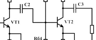
Radioelements
When reading circuit diagrams of devices, you need to know the symbols of diodes, resistors, and other similar elements.
Symbols of radioelements in drawings
Knowledge of conventional graphic elements will help you read almost any diagram - any device or electrical wiring. The values of the required parts are sometimes indicated next to the image, but in large multi-element circuits they are written in a separate table. It contains letter designations of circuit elements and denominations.