Currently, most residential owners prefer to use warm water floors for heating. The efficiency of this design depends on proper coolant flow.
Adjusting the flow meter of the underfloor heating manifold will allow you to monitor water consumption in the pipeline and fine-tune the system.
This device can facilitate the balancing process and rationally distribute liquid over the heating circuits, thereby creating uniform heating of all rooms.
The essence of the collector
The main feature of a water heated floor is the coolant; the water gradually moves to the heating circuit and gives off part of its energy.
That is why the heating of the floor occurs with the release of heat to the air that is mixed inside the room, and it, as is known, is directed from the bottom up. A number of devices are responsible for supplying warm water to the circuit and intensity:
- the valve is considered the main one;
- a pump must be present;
- collector.
All control of water distribution is carried out using a flow meter. It is this device that plays the main role in the operation of the entire system.
All collectors are designed specifically for hot water, and they are also necessary to collect waste material. In the unit itself, the process of mixing hot water that comes from the source and return takes place.
Thanks to rotameters, there is a chance to ensure that the entire volume of water reaches the floors. Simply put, the equipment will independently control the heat in the water field.
Floor heating cannot do without a rotameter. The design includes a body made of plastic, but there are models made of brass. A float is placed inside any device. There is a flask with a scale.
The float can move up and down and at the same time points to a certain division of the scale. Judging by it, it will be possible to judge the volume of coolant that circulates in the pipeline.
If we talk about theory, the system works without a device, but in this case the adjustment has to be done manually, relying on your own sensations.
The flow meter for the underfloor heating manifold plays an important role; if it is abandoned, the following problems will arise:
- the fact is that in the absence of a flow meter, some floor contours can be supplied with coolants, while the features of the room will not be taken into account;
- the energy consumption used to operate heating devices, for example, either gas or electricity, will be excessively increased.
Let's say you plan to simultaneously heat the bathroom and another room, for example, a bedroom. A gas-powered boiler will heat water for the bathroom and bedroom absolutely identically, that is, there will be one temperature regime. If you have the task of heating industrial or residential buildings on an industrial scale, use a double-circuit electric boiler. Such units differ from household devices of the same principle of operation in their increased thermal power. But they are placed in separate rooms and only on the floor.
It is important to install the equipment correctly; to do this, you need to screw the device itself into the collector socket. Fixation occurs due to the nut. When improving a heated floor, it is advisable to try to control the length of the heat pipeline of all circuits, without paying any attention to the configuration. This will simplify the adjustment of the system and it will still be possible to achieve normal temperature parameters.
But we must take into account that the bathroom is small in size, in order to heat it you need less water from the boiler, but more water is required to supply the bedroom. It is possible to compare the heat of each room, but only in this case will you need to use a flow meter.
If you use this device, the temperature will be set in the bathroom and bedroom for a comfortable stay there.
Having carefully assessed the principle of operation of this device, we can draw the following conclusions:
- the device can function completely autonomously, without the need to use any additional power sources;
- the main operating principle of the flow meter makes it possible to sufficiently consume the coolant for the circuit and further significantly reduce the energy costs of all heating devices;
- the design of the entire device is capable of providing control over the amount of water entering the pipes;
- the manifold, which is installed together with the flow meter, makes it much easier to control the operation of the entire system in general. Also, installation of the system is not complicated and does not require special maintenance.
Techniques for regulating the temperature of water floors
As already mentioned, there are many options to ensure that the room temperature is maintained at a comfortable temperature. Let's look at each of them.
Manual adjustment
The process is carried out using thermal heads (like a regular faucet). No automatic devices are needed. The thermal head is installed on the return and supply manifolds. The process is carried out after filling each circuit loop in the absence of air in the pipes. First, the main system is filled, then open/close the forward and reverse direction of the loop, to fill it too, the air must exit through the air duct, otherwise the floors will not heat as expected.
Having started the circulation of one loop, check the temperature - it should be approximately the same everywhere. Cast off the first stitch and move on to the next. In this way, all loops of the circuits are checked. Of course, when determining hot/cold only by hand, you cannot get a perfect match of the temperature of each loop, so sometimes the overall result can be seen only after an hour - the inertiality of the system makes itself felt.
Important! When manually setting the temperature mode, an imbalance of the system is possible. Therefore, sometimes you have to call specialists to completely reconfigure the heating.
Group regulation
It is used when it is necessary to maintain heat in several objects at once. This implies the use of automatic devices, which guarantees the accuracy of the result, providing greater control comfort. The adjustment is carried out at the heat source, as well as at the mixing units, using the principle of “constant” or “climate control”, covering the entire building.
- The constant principle is implemented using thermal heads mounted on two- and three-way valves. The sensitive system will always maintain one preset temperature. Large units are equipped with electric drives; for small units, conventional devices are sufficient.
- A water heated floor, regulated according to the “climate control” principle, depends on an automatic sensor installed on the system. It turns out that it is adjusted according to the general ambient temperature, and therefore everything is decided by automation. The “smart” system makes the calculations itself, setting the thermal mode and maintaining it for a specified time. This is done by calculating the temperature of the water and supply air, calculating the correspondence to the table, and then the machine calculates the optimal temperature gradation for the room.
Important! Group adjustment methods are a remote option and do not require constant human presence.
Individual regulation
As a rule, this option is suitable for providing a comfortable microclimate in a single room. In this case, the air temperature is determined, then the heated floor, and adjustment is ensured by installing a sensor in each zone (room). The group adjustment option will not replace the individual one, since in the first case the system covers the entire house, working in the “same rhythm”; in the second case, each zone has its own temperature regime of the water floor, which may be different from any other - the difference in temperature conditions circuits is sometimes quite significant, which is why the installation of temperature control sensors is required on an individual basis.
As for the last, comprehensive option for regulating the temperature regime of a water floor, it is achieved by correctly combining a group and individual solution. It is quite difficult to carry out such work on your own, especially if you do not have a certain skill - a large temperature difference can cause a malfunction of the entire system, so a complete reconfiguration of the structure will be required, which will entail additional costs.
If you are installing a heated floor system with your own hands, the simplest and most effective way to regulate the temperature of a water heated floor is to use taps, that is, the manual option. Installation does not require any professional skills, and it is quite convenient to work with them: cold - open, warm - close the supply of boiling water through the pipes of the system. In addition to simplicity, the method is characterized by economical implementation, and if the taps are located where children can reach them, there are thermal heads equipped with special protection that will prevent the possibility of torsion in a chaotic manner.
centro-pol.ru
Purpose and types
A warm water floor is distinguished by a large number of pipe circuits and a low temperature of the coolant circulating in them. Basically, heating the coolant to 35-40°C is required. The only boilers that can operate in this mode are condensing gas boilers. But they are rarely installed. All other types of boilers produce hotter water at the outlet. However, it cannot be run into the circuit at this temperature - a too hot floor is uncomfortable. To reduce the temperature, mixing units are needed. In them, in certain proportions, hot water from the supply and cooled water from the return pipeline are mixed. After which, through the manifold for the heated floor, it is supplied to the circuits.
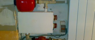
Manifold for underfloor heating with mixing unit and circulation pump
To ensure that all circuits receive water at the same temperature, it is supplied to a heated floor comb - a device with one input and a number of outputs. Such a comb collects cooled water from the circuits, from where it enters the boiler inlet (and partially goes to the mixing unit). This device - supply and return combs - is also called a manifold for heated floors. It can come with a mixing unit, or maybe just combs without any additional “load”.
Control elements
Setting up a heated floor collector is impossible without special devices. With their help, the optimal heating mode of the system is established and water flows in the pipelines are regulated. Each of them performs a specific function.
- Water temperature sensor
Installed on the inlet and outlet pipes of the device. These devices do not affect the operation of the system, but indicate the current heating rate. The difference in values can be useful in calculating operating efficiency. They also serve as an indicator of heating mode violations.
- Central thermostat with servo mechanism and sensor.
It is mounted on the inlet pipe of the inlet manifold and connected to the return pipe with cooled coolant. The temperature sensor is placed in the comb body. There is a rotary knob on the body of the thermostat with which you can set the required temperature level. The device receives readings from the sensor about the degree of water heating. Depending on this, the flow of cold and hot coolant is regulated.
- Servo drives on the inlet comb nozzles
According to the principle of operation, they are completely similar to a thermostat, but with minor additions. With their help, the volume of water flow for each circuit of the water floor is regulated. Depending on the model, this can be done in manual or automatic modes. For the latter, servos with built-in temperature sensors are used, which can be connected to a common remote thermostat.
- Flow meters
Devices that are optional for installation, but which, however, can become effective elements for manually controlling the operation of a water heated floor. They are installed on the return manifold pipes and are locking mechanisms with a glass bulb.
When you turn the head on the body, the rod in the device changes its position. This affects the volume of liquid passing through it. For clarity, a measurement scale is printed on the surface of the flowmeter, indicating the flow rate of water l/min.
How does the collector work?
Water floors are laid in various ways, for example, concrete or flooring, but regardless of the technology chosen, it is necessary to purchase and install a manifold cabinet.
In the future, two pipes will be inserted into it:
The cyclical nature of the process is ensured by another built-in component of the system - a circulation pump. One way or another, during the operation of a heated floor, say during repair work, the system has to be turned off. To do this, each of the pipes is equipped with shut-off valves. A plastic pipe and a metal shut-off valve are connected to each other through a compression fitting. Then a comb is connected to the valve, mounting an air vent on one end and a drain valve on the other. After assembling the cabinet, they proceed directly to installation. And only with a comb already installed on the wall can you cut the circuit pipes to length.
Settings
As a rule, a special balancing table is attached to the diagram, on the basis of which the comb can be adjusted according to two parameters: circuit length and heating load.
The table relates the circuit number and the number of revolutions from the position of the balancing valve - “closed”. Set up the comb like this:
- remove the cap from the valve that serves to protect it;
- close the valve all the way - use a hex key for this;
- determine the number of revolutions for a given circuit;
- turn off the valve to this number;
- The remaining circuits are configured in the same way.
Correct configuration and connection of the collector are necessary for long-term operation and efficient operation of the system.
Warm floor and the space occupied by the manifold with flow meters
The peculiarity of a heated floor as a heating system is that the heated coolant, moving along the heating circuit, transfers part of the thermal energy to the floor surface. Thus, by heating the floor, heat is transferred to the air mass circulating inside the room in the direction from bottom to top. A number of devices control the supply of warm water to the heating circuits, the intensity and flow rate, including:
- three-way valve;
- circulation pump;
- collector.
The distribution of the coolant is controlled by a flow meter for heated floors. This device plays one of the key roles in the operation of the entire pumping and mixing group. Heated floor collectors are designed to supply hot water and collect waste coolant for its further use in the heating system pipeline. In the pumping and mixing unit, hot water coming from the heating source is mixed with the coolant returned to the circuit - return. The functionality and efficiency of heated floors is based on this operating principle.
Mixing unit with rotameters for a warm water floor system
Together with the operation of safety valves, rotameters are designed to regulate the temperature of the coolant in individual circuits of the water floor. Thanks to these devices, the required volume of prepared water entering the warm water floor system is ensured. In other words, this equipment monitors the amount of coolant in the water heating pipe, and therefore the functionality of the entire heating system.
Select the bypass adjustment value 0-5 depending on the situation.
Using the example of these two mixers, we can now show the difference between the different bypass adjustments of the TIM JH-1036 mixing unit.
Bypass setting value is 0.
The first mixer operates in conditions where the bottleneck of the system is the heat supply from the system.
It is connected like a radiator in a one-pipe system.
Just in case, I made a thickening at the connection section from 25 to 32 diameters and installed a tap, since I doubted that a sufficient amount of water would flow in and provide sufficient power.
This local heating subsystem is built, of course, on one mixing unit without a collector group.
There should be no problems with circulation along one circuit.
Therefore, we set the value of the bypass adjustment bolt to 0.
We make the circulation through the heated floor circuit minimal, and the circulation through the mixing chamber maximum.
It was shown above that here the mixer pump will help the circulation through the heating system a little more.
Bypass setting value 5.
In this case, on the contrary, the heated floor mixer is connected directly to the boiler in parallel to a single-pipe system with batteries.
There are no problems with supplying the required thermal power to the mixer.
Typical connection diagrams
Water heated floors are rarely used as the only source of heating. Heating only due to underfloor heating is permissible only in regions with a mild climate, or in rooms with a large area, where heat removal is not limited by furniture, interior items or the low thermal conductivity of the floor covering. Almost always it is necessary to combine radiator circuits, hot water preparation devices and underfloor heating loops in one heating system.
Typical diagram of a combined heating system with connection of radiators and underfloor heating circuits. This is the most technologically advanced and easily customizable option, but it also requires significant initial investment. 1 - heating boiler; 2 — safety group, circulation pump, expansion tank; 3 - manifold for separate two-pipe connection of radiators in a star configuration; 4 — heating radiators; 5 - underfloor heating manifold, includes: bypass, three-way valve, thermostatic head, circulation pump, combs for connecting underfloor heating circuits with gearboxes and flow meters; 6 - heated floor contours
There are quite a large number of variations in the design of the boiler room piping, and each individual case has its own principles of operation of the hydraulic system. However, if you do not take into account very specific options, then there are only five ways to coordinate the operation of heating devices of various types:
- Parallel connection of the underfloor heating collector to the main line of the heating unit. The insertion point into the main line must be made up to the connection point of the radiator network; the coolant supply is provided by an additional circulation pump.
- Association according to the type of primary and secondary rings. The line, wrapped in a ring, has several supply connections in the supply part; the coolant flow in the connected circuits decreases with distance from the heating source. Flow balancing is performed by selecting the pump supply and limiting the flow with regulators.
- Connection to the extreme point of a coplanar manifold. The movement of the coolant in the heated floor loops is ensured by a common pump located in the generator part, while the system is balanced according to the principle of priority flow.
- Connection through a hydraulic separator is optimal when there are a large number of heating devices, a significant difference in flow rates in the circuits and a significant length of underfloor heating loops. This option also uses a coplanar manifold, but the hydraulic arrow is necessary to eliminate the pressure drop that interferes with the correct operation of the circulation pumps.
- Local parallel loop connection via unibox. This option is well suited for connecting a short-length heated floor loop, for example, if you need to heat the floor only in the bathroom.
The simplest option is to connect a heated floor circuit to a radiator heating system with a coolant temperature of 70-80 °C.
1 - line with supply and return of the high-temperature circuit; 2 - heated floor contour; 3 - unibox. It must be remembered that the nature of the operation of a heated floor may also change depending on the installation pattern of the coil. The “snail” scheme is considered optimal, in which the tubes are laid in pairs, which means that the entire area is heated almost evenly. If the warm floor is arranged as a “snake” or “labyrinth”, then the formation of colder and warmer zones is practically guaranteed. This drawback can be eliminated, including through proper configuration.
How pipes are laid
Polystyrene boards are laid on the leveled floor surface.
They serve as thermal insulation and prevent heat from spreading in all directions. The actual laying of pipes is carried out in two main ways: bifilar (parallel rows) and meander (spiral).
The first type is used when there is a slope of the floors, there is no need for strictly uniform heating. The second one requires more effort and precision and is used when using pumps of lower power.
The number of circuits depends on the size of the heated room. The maximum area for placing one circuit is 40 sq. m. The laying step can be either uniform throughout its entire length or vary depending on the need for enhanced heating in certain areas. The average step length is 15-30 cm.
Since the pipes experience strong hydraulic pressure, when installing a water heated floor, it is unacceptable to connect them using couplings. Only one coupling can be used for each circuit.
It is recommended to use one circuit for heating each room, including the bathroom, loggia, storage room, barn. The smaller the circuit, the higher its heat transfer, which is especially important for corner rooms.
Why do you need a flow meter?
Theoretically, it is quite possible to do without installing a flow meter in the manifold. However, if you do not install this device, then:
- Different rooms will have different temperatures;
- There may be excessive consumption of electricity to heat water in the system;
- Different circuits will heat up unevenly.
A simple example can be given: a bathroom and a bedroom. A gas or electric boiler heats water equally for both the bath and the bedroom. But the bathroom is at least 3 times smaller in area than the bedroom. Accordingly, the bathroom will be hot and the bedroom will be cool with the same water supply to the floor heating system. This situation is due to the fact that in the bedroom the total length of plastic pipes in the area is much greater. It is precisely in order to regulate a comfortable temperature in the entire apartment that it is desirable to install such a device.
Advice! When installing a water heated floor, you should strive to make the contours of the pipes approximately the same length. This will save energy costs and allow you to more accurately regulate the temperature.
Principle of operation
The device is installed on the return collector outlets. When the set temperature in the system is reached, the manifold valves narrow the lumen of the energy supply or close it completely. This principle of operation is possible with full automation of the system. For this purpose, the collector is equipped with a temperature sensor.
The flow meter itself consists of several parts:
The flask is usually made of durable glass; the body can be plastic or brass. The float is located inside the flask; it serves as an indicator of the coolant speed. The flow meter is also called a float rotameter.
In an automatic water heated floor collector, balancing of coolant flow is carried out using a temperature sensor. If the latter is not provided, then the rotameter can be adjusted manually.
Adjusting the device
The heating manifold has a built-in flow meter that monitors water flow.
A flow meter is installed on the return manifold outlets. It blocks or partially blocks the supply of energy at the moment when the set temperature is reached.
In some cases, the system is additionally equipped with a temperature sensor . If it is not there, the flow meter is adjusted manually.
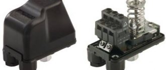
Photo 3. Flow meter on the heating manifold. The device controls water flow, thereby regulating the temperature in the system.
Installation of a system with flow meters
The flow meter is installed on the return of the collector, as recommended by the manufacturers.
However, a feed installation option is possible. The main and important requirement for installing the device is to place it strictly vertically . This facilitates the correct calculation of the coolant level. The collector is placed in a horizontal position.
Automatic operation of the collector and rotameter requires the connection of a temperature sensor. This allows you to block the access of water to the loops when the desired heating degree is reached.
Flow meter installation:
- The device is screwed into the collector socket with a key in a strictly vertical position. The rotameter has an O-ring and a nut.
- Twist and remove the flask by turning it counterclockwise. Remove the ring and return the flask to its original position.
- Turn the brass ring clockwise, bringing it to the desired value, to find the balance of the speed of incoming water.
- Place a cover over the ring to protect it from damage.
At the end of the process, the system is checked for functionality.
Rotameter installation
Let's consider how to correctly install the most commonly used type of water meter - combined with a valve integrated into it. The device is placed strictly vertically: it is simply screwed into the seat, onto the manifold comb on the supply or return. The option is prescribed in the technical documentation and depends on the direction of the liquid inside. The manifold already has sockets for the threads of rotameters as standard, and is often sold already assembled or as a set with them.
Additional sealing materials are not required, but if a leak occurs, they can be used. The standard product has a union locking nut and a polypropylene ring seal.
The traditional appearance of the unit diagram is as follows: water meters with valves on the supply segment, thermostats on the return segment (it can be the other way around).
On the comb of multi-circuit equipment collectors there are seats for each segment, that is, a larger number of water meters are used for each coil that needs to be configured. The device is fixed with a union nut; there may be other mounting options.
If thermostats are installed on the pumping and mixing part, then an additional adjustment to the water meters is also carried out: when the water reaches a certain t°, a valve is activated on the collector return, changing the gap for the flow of water.
The scale of the rotameter flask shows the flow; it is filled with water, the level of which varies depending on the intensity of consumption. There is also a float, which stops opposite the corresponding division. The water meter will immediately show the value, and balancing will be done with a few simple movements.
It is possible to adjust the warm floor contour correctly only if the liquid level in a transparent measuring container with a scale is strictly horizontal. Particular care must be taken to ensure that the device itself is installed exactly vertically. To do this, install the manifold with seats exactly, checking with a plumb line, bubble, and level. However, if the position of the node has deviations, then the system will work normally, but during adjustment it will be necessary to take into account errors.
Flowmeter functionality
A rotameter or, to give a full definition to this unit, a float rotameter, at first glance, is a common mechanical device. The design of the product is based on a plastic case (there are models made of brass), inside of which there is a polypropylene float. The body is equipped with a transparent bulb on which a marking scale is applied. The movement of the float up and down inside the device indicates a certain value on the scale, by which one can judge the volume of coolant circulating in the pipeline system - whether it is enough for the full operation of the heating circuits.
Traditional flow meter for underfloor heating manifold in various versions: on the left - in a plastic case, on the right - in brass.
From a theoretical point of view, the heating system can operate without this device. In this case, you will have to manually adjust the volume of water entering the circuit, based on your personal feelings when the air temperature in the room changes.
- individual circuits of the water floor will be supplied with coolant without taking into account the characteristics of the room, as a result of which the temperature values of the floor surface of heated rooms will differ;
- the energy consumption used to operate heating devices (electricity or gas) will be increased.
For example, you plan to heat the bathroom and children's room at the same time. An autonomous gas boiler will heat water for the bathroom and nursery in the same way, at the same temperature. However, the bathroom is smaller in area and will require less boiler water to heat it than to supply a heated floor in a nursery. You can achieve optimal supply of coolant to heated floors in each room using a flow meter. Consequently, due to the operation of this device, it will be possible to achieve individual temperature values for comfort in the bathroom and children's room.
Assessing the operation and principle of operation of the device, the following conclusions can be drawn:
- the device operates completely autonomously, without requiring additional power sources;
- the operating principle of the flow meter allows you to create optimal coolant flow for heating circuits, significantly reducing the energy consumption of heating devices;
- the design of the device provides visual control over the amount of water in the pipelines;
- the collector together with flow meters for underfloor heating significantly facilitates control over the operation of the entire system, is easy to install and unpretentious to maintain.
Water meter design
The design of the rotameter is mechanical, the material is plastic and/or metal (brass). The upper segment of measuring and adjustment models has a transparent tube with graduation.
There is a float inside, which is why the device is called “float”. This element, fixed to the rod, is supported by a spring (the flow changes the pressure, compresses/decompresses it). At the bottom inside there is a valve connected to the described elements, which changes the flow of liquid according to their position.
Criterias of choice
The quality of functioning of the underfloor heating system depends on the correct selection of the flow meter. Three types of rotameters are produced:
- Measuring. This type of flow meter is installed with a manual adjustment valve. Control is carried out taking into account measurement readings.
- Regulating. It performs only one function - controlling the amount of coolant entering the water circuits.
- Combined. Such a device combines two actions - adjustment and measurement. The cost of the product is significantly higher than that of models performing the same type of functions.
When purchasing a flow meter for heated floors, you should pay attention to the following product parameters:
- Case material. Devices made of brass have high wear resistance. The top of such a body should be covered with nickel. Plastic products are cheaper, but they have a reduced strength rating.
- Device integrity. Before purchasing a rotameter, it is recommended to carefully inspect the housing and transparent bulb to exclude the presence of cracks or other defects.
- Inner part. The spring in the middle of the flowmeter body should be made of stainless steel.
- Flask. The transparent cap with a measuring scale in high-quality models is made of polycarbonate. This material is quite strong and has high heat resistance, which is especially important when used in heating systems.
- Specifications. The instructions supplied with the device indicate the temperature level. This indicator should be no lower than 110 degrees. Also equally important is the pressure - at least 10 bar.
- Maximum throughput value. The rotameter must be able to conduct at least 2-4 meters of coolant through itself in an hour.
Flow meter for heated floors
You should also pay attention to the manufacturer of the product. The main indicator of the reliability of a product is the availability of a quality certificate and the provision of a guarantee, which responsible companies offer for up to five years.
How to save money on a mixing unit
Many master plumbers consider it an integral part of the underfloor heating manifold, although these are 2 different elements that perform separate functions. The task of the comb is to distribute the coolant along the circuits, and the mixing unit is to limit its temperature to 35-45 °C, maximum 55 °C. The collector connection diagram shown below works according to the following algorithm:
- While the system is warming up, the two-way valve on the supply side is completely open and allows maximum water through.
- When the temperature rises to the calculated value (usually 45 °C), the remote sensor acts on the thermal head, and it begins to block the flow through the valve, pressing on the rod.
- After the valve mechanism is completely closed, the coolant, stimulated to move by the pump, circulates only in a closed floor heating network.
- The gradual cooling of the water is detected by a temperature sensor, causing the thermal head to release the rod, the valve opens and a portion of hot water enters the system, while some of the cold water goes back. The heating cycle repeats.
Good news for those who are very limited in funds, but want to heat themselves with warm floors: installing a two- or three-way valve with a pump is not always necessary. There are two ways to reduce the cost of the system by avoiding the purchase of a mixer:
- power the heating circuits directly from the gas boiler through the manifold;
- install RTL thermal heads on the manifold valves.
The manifold assembly, assembled from brass tees, provides for regulation by automatically limiting the reverse flow with RTL heads.
Let us immediately note that the first option contradicts all the canons and cannot be considered correct, although it is used quite successfully. The bottom line is this: high-tech wall-mounted gas boilers can maintain the temperature of the supplied water at 40-50 °C, which is acceptable for heated floors. But there are 3 negative points:
- In spring and autumn, when there is minimal frost outside, the boiler will not be able to lower the coolant temperature below 35 ° C, causing the rooms to become stuffy and hot due to heating of the entire floor surface.
- In the minimum combustion mode, the parts of the heating unit are covered with soot twice as quickly.
- Due to the same mode, the efficiency of the heat generator is reduced by 5-10%.
Thermostatic heads of the RTL type operate on the principle of a two-way valve, only they are located on each circuit and are not equipped with remote sensors. A thermoelement that responds to changes in water temperature is located inside the head and blocks the flow along the circuit when it has heated up above 45-55 ° C (depending on the adjustment). In this case, the comb is connected directly to a heat source running on any type of fuel - wood, diesel or pellets.
Important condition. For normal operation of heated floors controlled by RTL thermal heads, the length of each circuit should not exceed 60 m
More details about the design of such heating and the correct schemes for assembling the collector are described in a separate instruction and in the next video:
Installation and configuration of a heated floor collector - how to do it
Where to place the collector
It is recommended to place the collector above the level of all connected circuits. Automatic air vents should be located on the combs, and be at the highest point of the entire floor heating system. If you don’t want the floors to not work and become airy, you need to maintain the level.
The distance from the finished floor to the connection point of the pipes on the combs should be such that no obstacles are created for the convenient connection of pipelines coming out of the screed.
More often, collectors are assembled by the manufacturer for connection “on the left”. If it is necessary to connect “on the right”, the product components are rearranged in accordance with the instructions.
It may also be necessary to rotate the pump 90 degrees in order to reduce the overall size of the product. This is usually not difficult to follow the instructions.
Consolidation
The easiest way to fix the collector is to use a special cabinet, built-in or wall-mounted.
Use standard mounting schemes provided by the manufacturer. Use a special cabinet or racks, shields with vibration dampers.
Equipment, collector design
Let's look at the installation of a collector using the example of a product from one of the manufacturers.
This collector is assembled according to a common scheme and includes standard components.
- 1. Circulation pump.
After fixing the collector, underfloor heating loops and supply pipelines are connected to it, while all valves and taps must be closed.
Coolant in the system
An important issue is preventing oxygen from entering the system. It is necessary to use materials, parts, and units with minimal permeability to oxygen.
How to fill a heated floor system
The underfloor heating system is filled with coolant through the drain valves on the manifold. The connected loops are filled one by one.
To do this, the control valves (thermostatic and balancing) of only one circuit are opened alternately, while all other valves on the manifold must be closed.
- Bypass valves 5, thermostatic valve 3, trim valves 2 and 4 are closed.
It is recommended to carry out hydraulic tests of the entire underfloor heating system. To do this, the pressure in the manifold and circuits rises to at least 1.43 from the working pressure, but not below 3 atm, for at least 2 hours.
Setting the flow rate in the collector based on coolant temperature
Commissioning and initial setup of the underfloor heating collector are as follows:
- Valve 2 is completely open.
3 completely open.
4 completely closed.
Pump 1 is on.
During the first few days (as well as during operation), it is possible to further configure the system with valve 4 according to the situation and preferences.
Installation and adjustment of the pump
Depending on the required performance, a 15-40 pump can be installed for 2 - 6 collectors or a 15-60 pump for 7 - 10 collectors.
Both pumps without electronic control, such as UPS, and modern ones with electronic control, such as ALPHA2L, can be used.
In the first case, the settings are limited to the “Fixed speed” modes. Depending on the heated area, it is possible to use 1, 2 or 3 speeds, and the temperature difference between supply and return should be within 5 - 10 degrees.
How to balance underfloor heating circuits
The collector is balanced (initial setting) using balancing valves. It is necessary to equalize the pressure drop between the circuits and supply the required amount of coolant to each circuit.
- Use a 5 mm hex key to remove the cover (A).
To install the servo drive on the thermostatic control valve, remove the manual control handle (A), install the adapter ring (B) on the valve, insert the servo drive into the grooves of the adapter ring, and turn the adjusting ring clockwise until it clicks.
Rules for refueling the system
Setting up the operation of a heated floor cannot be done if the coolant flow in the loops changes spontaneously. This phenomenon is typical when there are air locks, so the heating system must not only be properly organized technically, but also properly charged.
To fully fill the system, automatic air vents must be installed on both branches of the underfloor heating collector. If the loops are located at a level above the collector, the supply connection to the latter must be made through a deaerator. Refilling the underfloor heating system is carried out separately from other heating circuits, that is, the piping of the generator part and the radiator network must be filled in advance, and the shut-off valves at the collector inputs must be closed.
To fill the coolant into the system, a hose from the water supply system or pump is connected to the drainage outlet of the supply branch of the collector. Accordingly, a hose must be connected to a similar outlet of the return branch to bleed the air, the return end of which is either led outside or lowered into a container with a volume of 30–40 liters.
The first thing to fill in a heated floor system is the manifold and its piping. In this case, the flow meters on the supply branch must be completely open, and the regulators on the return branch must be closed. Next, you need to sequentially fill each loop with coolant until clean coolant without air bubbles comes out of the bleed hose. The heated floor is filled with a minimum flow to uniformly squeeze out air from the system. When all the underfloor heating loops are filled, you can put the heating system into operation and balance it.
Features of adjustment
For each individual room, the rotameters are adjusted separately. Control is carried out according to the diagram of the installed circuits
In this case, the level of heating of the liquid and pressure is taken into account
It is recommended to carry out balancing according to the following instructions:
- The total amount of coolant passing through the collector in one minute is determined. Indicators are taken in liters. The resulting value is taken as 100 percent.
- The percentage flow rate of each individual water circuit is calculated. The result is converted to liters per minute.
- The flow meter regulates the amount of liquid supplied to the pipeline.
Using these steps, you can perform long-term adjustments to the water circuit. To indicate the actual parameters, it is necessary to observe the flow meter readings. According to observations, it is possible to accurately determine the flow rate of the circuits connected to the collector.
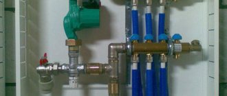
Manifold with flow meters for heated floors
The flow meter is adjusted depending on the installed model. After connecting the device to the manifold, preliminary settings should be made by setting the initial position, which allows access to liquid.
In rotameters without a built-in valve, an additional locking device is used to set the “open” position. In this case, balancing is performed during the operation of the system.
Combination devices for metering coolant flow can be pre-set using full turns of the built-in valve. Each turn allows you to reduce the clearance by a set value.
Adjustment of the flow meter of the floor heating system is carried out taking into account the control of the fluid speed in one minute - from 0.5 to 5 liters.
Before setting up the rotameter, you should check the condition of the installed circuit. Trial testing is necessary to exclude the presence of leaks in the circuit, which could cause distortion of the indicators in the device.
The flow meter is an important element in a multi-circuit underfloor heating system. The device allows for a uniform flow of liquid into all individual pipelines. In order for heating equipment to function as efficiently as possible, you must select the right rotameter, as well as install and configure it in accordance with technical requirements.
Finally, the heating system of my house is assembled. The boiler is started. Let me remind you that I decided to heat my house only with heated floors. Although there are not many rooms in the house, in order for the comfort in all rooms to be the same, it is necessary to adjust the heated floor. We will talk about how to set up a heated floor in this article.
Setting up a heated floor is not as complicated as it might seem at first glance. Generally speaking, setting up a heated floor consists of three stages. First, balancing the underfloor heating loops, then setting up the pump and mixing unit, and finally setting up the controller if you decide to automate the heating system. I decided to fully automate the heating system in my house. Therefore, I purchased a controller, servos and temperature sensors. Let's look at the first stage of setup in detail, since the success of the entire setup depends on how well it is done.
Calculation
Calculating what heating temperature is required to heat a particular room can only be done experimentally, that is, the user must try several settings, analyzing the time to achieve a comfortable environment in the room and the temperature level there. Fortunately, this is much easier to do with a rotameter than fiddling with the supply valves and pump manually.
There are no fixed values for rooms; this nuance is due to the fact that many factors influence heat retention in a room: thermal insulation, area, length of the coil, and the like.
On combined models, you can make a preset (usually this is done) by the number of valve revolutions - each full turn reduces/increases the clearance by a fixed value. You can use the following method:
- First, the volume of coolant required for each circuit is calculated, its percentage relative to the total amount of liquid for the entire system.
- Based on the result obtained, the initial position of the valve (ring) is set for each section.
- The final adjustment of the flow meter is made during the operation of the system, based on the actual established temperature, according to feelings of comfort.
As we have already noted, for one or two rooms or rooms with identical parameters, a collector group with flow meters is desirable, but not as significant as for houses and apartments where several zones of different sizes are heated.
With equal coolant flow for the circuits of a large and small room, achieving the desired temperature in them will be different. The larger the area, the lower the quality of thermal insulation, the lower the level of heating will be. Accordingly, larger rooms will require a more intense and significant flow. And, conversely, in a smaller object you need to set the flow rate lower, otherwise it will be hot. But there is also a nuance here: if it has poor thermal insulation, then the values may become equal.
As you can see, the calculation is influenced by many factors; the comfortable mode even depends on the time of year. Adjustment is also called balancing, since the limited resource from the boiler is distributed; a change on one coil affects the others. Tuning can be done frequently, so the simplicity provided by flowmeters is highly sought after.
Let's give an example. Inside the house, an underfloor water heating system is installed for the bathroom and another room, for example, for the living room. Without a rotameter, a gas boiler will heat the liquid for the specified rooms equally, and one temperature regime will be established. It may be comfortable for the living room, but it will be hot in the bathroom.
For heating the first one requires more heated water from the boiler, for a small bathroom less. A water meter will allow you to quickly and comfortably bring the temperature of each room to the same level or set it to a different, but comfortable level, taking into account the characteristics of the room.
Also, when balancing, it is important to pay attention to the length of the circuit tubes, regardless of its configuration.
Let us note some more advantages of flow meters; the device will allow:
- it is easy to control the volume of liquid of a certain temperature sent for heating, which also entails the opportunity to more rationally manage the energy source (boilers). If it is of an electric type, then this nuance is very relevant;
- warm all branches evenly, avoid temperature fluctuations, which will increase comfort. On the other hand, it will allow you to turn off the heating where it is not needed, or reduce/increase it as desired by the user;
- You can visually monitor the volume of coolant flowing from the boiler through the main pipes. By looking at the flow meters, their bulbs with graduations and indicators, you can immediately determine visually the heating level of the room (you will also need to compare its dimensions and other parameters) and how much resource is being consumed.
Methods for adjusting the temperature of heating floors
To achieve the required temperature values that meet standard standards, you need to configure the device.
Correct adjustment of heated water floors is possible taking into account the type of room. The suitable temperature level for residential premises is from 20 to 28 degrees. For a kitchen, hallway or bathroom, heating from 19 to 24 degrees is suitable.
For your information! The permissible air humidity in the room is 60%, but 40 - 50% is considered optimal.
The main purpose of regulation is to ensure a constant temperature difference between the inlet and outlet. To determine the temperature difference, the thickness and material of the screed and the laying pitch of the pipes are taken into account.
The methods of adjusting the structure are influenced by the installed equipment; it can be mechanical or automatic. The device responsible for water flow is adjusted; this can be done by mixing hot and cooled coolant, or by limiting it.
Automatic adjustment
If underfloor heating is adjusted automatically, then the main adjustment elements are the RTL thermal head or the unibox valve. The level of heating of the floor depends on the set indicator; the higher it is, the hotter the liquid running through the pipes will be, and therefore the floor covering will warm up more strongly.
How to automatically adjust a water heated floor - this can be done in two ways:
- Using a thermostatic self-regulating device, adjustment is made using valves or a tap with heads.
- Using an electronic system, it includes an electric thermometer, a controller, and electric drives.
Electronic control devices are expensive, but with their help you can program floor heating and set it up for optimal and efficient operation.
Electronic regulators are represented on the market by many companies, the most popular being Onor products.
Manual temperature equalization
The manual setup process is simple but time-consuming. The water heating temperature is adjusted by opening or closing the valves. The procedure becomes much simpler if you have a device that meters the supply to each branch.
For your information! Heating floors will function effectively with manual settings - with intensive water circulation in the pipeline, this can be achieved using a separate heat pump.
Before you start adjusting the temperature level in the water floor, you need to make sure that the system is full and there are no air pockets. Setting is the supply of coolant to each coil and setting its flow rate. Control is carried out taking into account the difference in flow temperature at inlet and outlet. This procedure must be carried out annually.
Important! The temperature of the incoming coolant and the exhaust coolant in all loops should be approximately the same, the permissible difference is 5 - 15 degrees.
Monitoring the adjustment process of the water floor will make it easier to use a thermometer, laser or electric. Its presence will significantly reduce setup time.
Three-way valve capabilities
If the comb has a three-way valve, then the adjustment is done using a servo drive. In this case, the mixing valve will control the indicators. During this process, the three-way valve can be turned as desired and as many times as necessary. But setting the mixing valve is more difficult.
Why do you need a comb for a heated floor? Let's look at its structure and operating principle, how to choose it, instructions with photos and videos on how to install and configure it or do it yourself.
There is another opportunity to adjust heating floors - using a modular mixer, it consists of:
- three-way valve;
- thermometer;
- bypass;
- pump for liquid circulation;
- thermostatic head;
- relay.
This set costs a lot, but its effectiveness is high. There is a prerequisite for the functioning of this module - European assembly.
Another method of adjusting heated floors is to install a servo drive and a thermostat. The thermostat notifies the servo drive about the temperature drop in the room and the need to supply heated coolant. This method works even when assembling the collector yourself.
A warm water floor is a complex structure, and when you decide to build it in your home, you need to be aware that it is not enough to install the system, you must periodically adjust it according to the instructions. And it is important to understand this process, otherwise the floor will not live up to your expectations.
Optimal temperature parameters
Setting up a water heated floor is carried out depending on individual needs. Some people like it when the room is warm, while others prefer invigorating freshness, even in the most severe frosts. But despite this, there are general standards that were developed taking into account sanitary standards, these include:
- floor heating up to 28 degrees;
- if there is another heat source or if you live indoors permanently, the ideal level is from 22 to 26 - these are optimal conditions for a person;
- if this type of heat source is the only one, or it is located in the bathroom, corridor, balcony, or in a house where people do not live permanently, it is permissible to raise the degree to 32.
Therefore, when regulating water floors, in addition to your preferences, so that the microclimate in the apartment is healthy, you should take these standards into account.
Other Important Factors
In addition to the settings on the thermostat and the floor heating curve, other factors also play a role. It should be noted in advance that underfloor heating has different heating circuits. Here too the flow and return are separated. They are found in the so-called heating circuit. This allows home owners to regulate the space in different ways.
If it is necessary to hydraulically balance the heater to ensure optimal temperature distribution, this must also be taken into account. By the way, this should always be done by a specialist who sets different pressures for each circuit. So what should the flow rate be for it to become warm enough?
The following factors should be noted:
- Required heating power in the respective room
- Flow rate
- Pipe length
- Grounding and its thickness
- appropriate supply temperature
Conclusion
Adjusting floor heating has many practical advantages. It will give you more comfort by making changes to the thermostat in terms of automation. In addition, the above settings can of course also reduce energy costs, especially if the shutdown is chosen intentionally. Changing the heating curve, however, ensures ideal heating of the room and optimal energy use, depending on the season.
HelpfulUseless
High quality flow meter
In the store you may encounter a wide selection of different rotameters, so in order to choose a high-quality copy, you can select it according to the following characteristics:
- The flowmeter must have a high-quality housing without chips or protrusions. The body material is brass, but the top is coated with nickel.
- The internal spring of the rotameter must be made of stainless steel.
- Polycarbonate is an example of an ideal material for a transparent flowmeter bulb, because this material can withstand high temperatures, as well as some physical influences.
- It is impossible to determine this in a store, so you will have to trust the manufacturer and pay attention to the indicators: the device must withstand temperatures up to 110°C, as well as a pressure of 10 bar.
- The maximum throughput of the rotameter should not be lower than 2-4 cubic meters per hour. The measuring scale must correspond to these readings.
- The warranty for these products is long, often from 5 years.
Conclusion
A manifold for a warm water floor with flow meters allows you to control the flow of coolant, which ensures a comfortable floor temperature in any room connected to this circuit. This method of organizing a heated floor system additionally saves money, because you spend less energy on heating water.
Sources
- https://TeploRes.ru/ustrojstva-i-pribory/rashodomer-teplonositelya-2.html
- https://MasterpoToku.ru/full/kak-podklucit-kollektor-teplogo-pola-7-osibok-i-avtomaticeskoe-regulirovka-temperatury.html
- https://ZnatokTepla.ru/teplyj-pol/kollektor-s-rashodomerami-dlya-teplogo-pola.html
- https://mr-build.ru/newteplo/regulirovka-teplogo-pola.html
- https://lucheeotoplenie.ru/teplyj-pol/regulirovka-kollektora-teplogo-pola.html
- https://okcomfort.com/pol/pol-s-podogrevom/vodyanoj-teplyj-pol/kak-nastroit.html
- https://mr-build.ru/newteplo/rashodomer-dla-teplogo-pola.html
- https://OmShantiDom.ru/teplyj-pol/vodyanoj-teplyj-regulirovka-temperatury.html
- https://polspec.com/teplyy-pol/kak-vybrat-i-ustanovit-raskhodomer-dlya-teplogo-pola.html
What do you think of this article?
Both distributor and regulator
At its core, a distribution comb is a centralized unit that allows the coolant to be distributed to its destination points. In a heating system, it performs no less important function than a circulation pump or the same boiler. It distributes heated water through the mains and regulates the temperature.
This diagram shows the general operating principle of a collector block consisting of two combs: through one, coolant is supplied to the system, and through the second it is returned
This unit can be called a temporary coolant storage tank. It can be compared to a barrel filled with water, from which the liquid flows not through one hole, but through several. In this case, the pressure of water flowing out of all holes is the same. This ability to simultaneously ensure uniform distribution of heated liquid is the basic principle of operation of the device.
Externally, the collector looks like an assembly of two combs, most often made of stainless steel or ferrous metal. The terminals available in it are intended for connecting heating devices to it. The number of such outputs must correspond to the number of heating devices served. If the number of these devices increases, the unit can be expanded, so the device can be considered dimensionless.
In addition to the leads, each comb is equipped with locking mechanisms. These can be two types of taps installed at the outlet:
- Cutting off. Such taps make it possible to completely stop the supply of coolant from the general system to its individual circuits.
- Regulatory. With the help of these taps, the volume of water supplied to the circuits can be reduced or increased.
The manifold includes valves for draining water and releasing air. It is also most convenient to place measuring equipment in the form of heat control meters here. In this case, everything that is necessary for the effective operation of this node will be in one place.
Why are there two combs in the manifold block? One serves to supply coolant to the circuits, and the second is responsible for collecting already cooled water (return) from the same circuits. All elements necessary for effective operation must be on each of the combs.