Help the site, share with friends:
Installation height of the shield in the apartment
Important information
Methods for ordering services:
Secretary:
Requirements for switchboard and distribution devices
Switchboard rooms are not allowed to be located under toilets, bathrooms, showers, kitchens, sinks, washing and steam rooms, laundry rooms, dry cleaners, etc. Pipelines and ducts laid through switchboard rooms should not have branches, hatches, valves, or flanges. The laying of gas pipelines and pipelines with flammable liquids, sewerage and internal drains through these premises is not allowed (clause 7.1.29 of the PUE). Panel doors must open outward. Switchboards must have natural ventilation and electric lighting, heating, providing a temperature not lower than +5 ° C (clause 7.1.30, PUE). Switchboard rooms must be equipped with protective equipment and first aid equipment in accordance with clause 1.1.36 of the PUE. The switchgear must have clear inscriptions indicating the purpose of individual circuits and panels on the front side of the device (clause 4.1.3 PUE). All metal parts of the switchgear must be painted (clause 4.1 PUE). The switchgear must be grounded (clause 4.1 PUE). Switching device drives must clearly indicate the “On” position. and "Off" (clause 4.1.11 PUE). The color designation of tires must comply with clause 1.1.29 of the PUE: the most distant one is yellow (A), the middle one is green (B), the closest one is red (C); in the vertical plane: A-B-C - from top to bottom or from left to right. DC buses: positive (+) - red, negative (-) - blue, zero operating (M) - blue. The most distant is M, the middle is (-), the closest is (+); in the vertical plane: M, (-), (+) from left to right or from top to bottom. A zero working tire is indicated in blue, if the same tire is used as a zero protective tire - blue along the entire length and stripes of yellow and green at the ends (clause 1.1.29 of the PUE). The color designations of the wires must comply with clause 2.1.31 of the PUE: blue - neutral working or middle conductor; green-yellow - protective or zero protective conductor; green-yellow with blue marks at the ends - combined zero working and zero protective conductor. Phase conductors: black, brown, red, purple, gray, pink, white, orange, turquoise. Apparatuses and instruments should be located so that sparks or electric arcs arising in them during operation cannot cause harm to operating personnel, ignite or damage surrounding objects, or cause a short circuit or ground fault (clause 4.1.8 of the Electrical Installation Regulations). If the input panel of a multi-panel ASU has two input blocks connected to different power supply networks, then they must be separated by a partition. A partition should also be provided between the ATS input devices (GOST R 51732-2001, clause 6.2.10). In single-panel and cabinet-mounted ASUs, input and distribution units should be separated by partitions (GOST R 51732-2001, clause 6.2.11). If one distribution panel of a multi-panel ASU contains two distribution units connected to different inputs, then a partition must be provided between them (GOST R 51732-2001, clause 6.2.12). It must be possible to relieve voltage from each switching device during its repair or dismantling. For this purpose, switches or other disconnecting devices must be installed in the required places (clause 4.1.12 of the Electrical Installation Code). Installation of instruments and devices on switchgear and low-voltage switchgears should be carried out in an area from 400 to 2000 mm from the floor level. Manual operational control devices (switches, buttons) are recommended to be installed at a height of 700 to 1900 mm from the floor level. It is recommended to install measuring instruments so that the scale of each instrument is at a height of 1000 to 1800 mm from the floor (clause 4.1.14 PUE). Between fixedly fixed non-insulated current-carrying parts, as well as between them and non-insulated non-current-carrying metal parts, distances of at least 20 mm along the insulation surface and 12 mm in the air must be provided. Distances of at least 40 mm must be provided from non-insulated live parts to the fence (clause 4.1.15 PUE). In electrical rooms, service passages located on the front or rear side of the switchboard must meet the following requirements: 1) the clear width of passages must be at least 0.8 m, the height of clear passages must be at least 1.9 m. The width of the passage must ensure comfortable maintenance of installation and movement of equipment. In some places, passages may be constrained by protruding building structures, but the width of the passage in these places must be at least 0.6 m; 2) the distances from the most protruding unfenced insulated live parts (for example, disconnected knife switches) when they are located on one side at a height of less than 2.2 m to the opposite wall, fence or equipment that does not have unfenced uninsulated live parts, must be no less than: 1.0 m - for voltages below 660 V for a board length of up to 7 and 1.2 m for board lengths of more than 7 m, 1.5 m - for voltages of 660 V and above. The length of the shield in this case is the length of the passage between two rows of a solid front of panels (cabinets) or between one row and a wall; 3) the distances between unfenced non-insulated live parts and those located at a height of less than 2.2 m when they are located on both sides must be at least: 1.5 m - for voltages below 660 V; 2 m - at voltage 660 V and above; 4) non-insulated live parts located at distances less than those given in paragraphs. 2 and 3 must be fenced. In this case, the width of the passage, taking into account the fences, must be no less than specified in paragraph 1; 5) unfenced, non-insulated live parts located above passages must be located at a height of at least 2.2 m; 6) fences placed horizontally above passages must be located at a height of at least 1.9 m; 7) passages for servicing shields with a shield length of more than 7 m must have two exits. Exits from the passage on the installation side of the switchboard can be made both into the switchboard room and into a room for other purposes. If the service passage width is more than 3 m and there are no oil-filled devices, the second exit is not necessary. Doors from switchgear rooms must open towards other rooms (with the exception of switchgears above 1 kV AC and above 1.5 kV DC) or outwards and have self-locking locks that can be unlocked without a key from the inside of the room. The width of the doors must be at least 0.75 m, height - at least 1.9 m (clause 4.1.23 PUE). Entrances to buildings must be equipped with a VU or ASU. Before entering the building, it is not allowed to install additional cable boxes to separate the service scope of external supply networks and networks inside the building. Such separation must be carried out in the ASU or main switchboard (clause 7.1.23 of the Electrical Installation Regulations). VU, ASU, main switchboard must have protection devices on all inputs of supply lines and on all outgoing lines (clause 7.1.24 PUE). Electrical circuits of VU, ASU, main switchboard, VRShch, distribution points, group panels should be made with wires with copper conductors (clause 7.1.31 PUE). After the meter, protection devices must be installed on the group lines (clause 7.1.65 of the PUE). A switching device must be installed in front of the meter to relieve voltage from all phases connected to the meter (clause 7.1.64 PUE).
Note! Replacing the apartment panel
Design of a standard circuit breaker
For example, we will use the BA47-29 series switch as the most popular switching device with an affordable pricing policy. Before you learn how to properly connect a circuit breaker to a single-phase network, you need to consider its design.
The BA47-29 series circuit breaker consists of the following elements:
- A copper terminal connected to a fixed power contact. Most often, the supply wire is installed exactly in this place.
- The movable contact, which makes the switching, and the copper stranded conductor, has a sufficiently large cross-section.
- Arc chamber.
- A special thin plate with a hole through which gases formed after the arc escape.
- An electromagnetic release, presented in the form of a simple coil. The stranded conductor from the moving contact is soldered to the coil.
- Plastic, fully dielectric handle.
- A bimetallic plate that acts as a thermal release. The plate is located immediately behind the reel.
- A special screw for adjusting the bimetallic plate. The screw is not installed on all models, and adjustment is made at the manufacturer.
- The lower copper terminal, from which the conductor goes directly to the consumer.
A three-phase machine has a similar design, but instead of one terminal, it uses three, isolated from each other.
Input devices, distribution boards, distribution points, group boards
7.1.22. A VU or ASU must be installed at the entrance to the building. One or more VU or ASU may be installed in a building. 
If there are several economically separate consumers in a building, it is recommended that each of them install an independent VU or ASU. 
The ASU is also allowed to supply power to consumers located in other buildings, provided that these consumers are functionally connected. 
For branches from overhead lines with a rated current of up to 25 A, the VU or ASU may not be installed at the inputs to the building if the distance from the branch to the group panel, which in this case performs the functions of the VU, is no more than 3 m. This section of the network must be carried out with a flexible copper cable with with a conductor cross section of at least 4 mm, flame retardant, laid in a steel pipe, and the requirements for ensuring a reliable contact connection with the branch wires must be met. 
For air input, surge suppressors must be installed. 
7.1.23. Before entering buildings, it is not allowed to install additional cable boxes to separate the service scope of external supply networks and networks inside the building. Such separation must be carried out in the ASU or main switchboard. 
7.1.24. VU, ASU, main switchboard must have protection devices on all inputs of supply lines and on all outgoing lines. 
7.1.25. Control devices must be installed at the input of supply lines to the VU, ASU, and main switchboards. On outgoing lines, control devices can be installed either on each line, or be common to several lines. 
A circuit breaker should be considered as a protection and control device. 
7.1.26. Control devices, regardless of their presence at the beginning of the supply line, must be installed at the inputs of the supply lines in retail premises, utilities, administrative premises, etc., as well as in consumer premises that are administratively and economically isolated. 
7.1.27. The floor panel must be installed at a distance of no more than 3 m along the length of the electrical wiring from the supply riser, taking into account the requirements of Chapter. 3.1. 
7.1.28. VU, ASU, main switchboard, as a rule, should be installed in electrical switchboard rooms accessible only to maintenance personnel. In areas prone to flooding, they should be installed above the flood level. 
VU, ASU, main switchboard can be located in rooms allocated in operational dry basements, provided that these rooms are accessible to maintenance personnel and are separated from other rooms by partitions with a fire resistance limit of at least 0.75 hours. 
When placing VU, ASU, main switchboards, distribution points and group panels outside electrical switchboard rooms, they must be installed in places convenient and accessible for maintenance, in cabinets with an enclosure protection degree of at least IP31. 
The distance from pipelines (water supply, heating, sewerage, internal drains), gas pipelines and gas meters to the installation site must be at least 1 m. 
7.1.29. Electrical switchboard rooms, as well as VU, ASU, main switchboards, are not allowed to be located under toilets, bathrooms, showers, kitchens (except for apartment kitchens), sinks, washing and steam rooms of bathhouses and other rooms associated with wet technological processes, except in cases where Special measures have been taken for reliable waterproofing to prevent moisture from entering the premises where the switchgear is installed. 
It is not recommended to lay pipelines (plumbing, heating) through electrical rooms. 
Pipelines (plumbing, heating), ventilation and other ducts laid through electrical switchboard rooms should not have branches within the room (with the exception of a branch to the heating device of the switchboard room itself), as well as hatches, valves, flanges, valves, etc. 
Laying gas and pipelines with flammable liquids, sewerage and internal drains through these premises is not permitted. 
Doors to electrical rooms must open outward. 
7.1.30. The premises in which ASUs and main switchboards are installed must have natural ventilation and electric lighting. The room temperature should not be lower than +5 °C. 
7.1.31. Electrical circuits within the VU, ASU, main switchboard, distribution points, group panels should be made with wires with copper conductors. 
Option 5
In this option, difavtomats and conventional circuit breakers are used to protect groups. Automatic residual current switches (RCBOs) protect the cable from overload, from the action of short circuit current and protects a person from electric shock. Each difavtomat must be supplied with a phase and a zero. After logging out of these devices, you cannot combine zeros either. The neutral working conductors of the remaining groups, which are protected by conventional circuit breakers, are connected to the input common zero bus.
This article presents the simplest options for single-phase electrical panels. They discuss almost all protective devices, show how they need to be connected and contain descriptions of the use of one or another option. Based on your individual situation, you must develop your own scheme. Remember that it must meet all modern electrical safety standards.
Pipelines
It is not recommended to lay pipelines (plumbing, heating) through electrical rooms.
Pipelines (plumbing, heating), ventilation and other ducts laid through electrical switchboard rooms should not have branches within the room (with the exception of a branch to the heating device of the switchboard room itself), as well as hatches, valves, flanges, valves, etc.
Laying gas and pipelines with flammable liquids, sewerage and internal drains through these premises is not permitted.
Doors to electrical rooms must open outward.
7.1.30. The rooms in which the ASU (input switchgear) and main switchboard (Group distribution board) are installed must have natural ventilation and electric lighting. The room temperature should not be lower than +5°C. 7.1.31. Electrical circuits within the VU (Input device), ASU (Input distribution device), Main switchboard (Group distribution board) of distribution points, group panels (apartment panels) should be made with wires with copper conductors.
That's all about installing an apartment electrical panel according to the rules! Good luck to you in your endeavors!
Safety precautions
The shield is operated by trained workers . Emergency work is carried out by field operatives. Repairs begin only after de-energizing the switchgear. They put up warning signs about the work prohibiting turning on switches.
In the panel under each switch there are clear markings and inscriptions indicating that the device belongs to a specific circuit . They use adhesive stickers on which short informative messages are written.
If the cable is damaged, it cannot be repaired, it can only be replaced.
Work is performed on a rubber mat or in current-insulating shoes. Wear rubberized gloves, and the tool handles should be insulated.
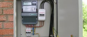
Purpose of the distribution panel
The distribution of power in an apartment building occurs according to the following scheme. From the transformer substation, the power supply cable is introduced into the house and connected to the input device (ID) and/or the main distribution board (MSB). From the input devices, the supply circuit “delivers” power to the floor panels, and from them, through distribution circuits, it “distributes” to the apartments where the apartment panels are powered. From the apartment panel, the power supply is distributed through group circuits throughout the apartment to sockets, lamps and stationary electrical appliances.
This is precisely the power supply scheme for an apartment originally, in ancient times, and remains in many old houses. According to old standards, distribution panels with fuses and a meter were installed in apartments, as in the photo.
Then the apartment panels were removed from the apartments, and the accounting and distribution of power supply to the apartments were concentrated in the floor panels.
In modern residential buildings, after the adoption of the new PUE edition 7.08.07.2002, apartment panels were “returned” to apartments. At the same time, the aluminum wiring was replaced with copper and all electrical wiring in the apartment acquired a more civilized appearance.
But not everyone lives in new houses, and the increase in electrical appliances in the apartment simply requires bringing the apartment’s electrical wiring into a modern, and most importantly, safe form.
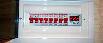
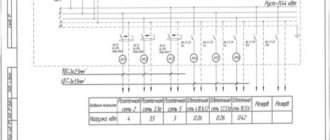
Electrical panel diagram
When drawing up a diagram of an apartment electrical panel, the following should be taken into account:
- The total power of consumers of the apartment's power supply system;
- Number of consumer groups;
- Power of each group;
- Place of installation of the electric meter.
The diagram must indicate all the components of the shield, indicating the full name, rating and protection class - this is necessary for replacing components or additionally installing new ones.
In old Soviet-built houses, the wiring was not grounded; accordingly, on the electrical panel diagrams of apartments in such buildings, as in fact, there will be no grounding bus. If the house is newly built, or the building’s power supply system has been reconstructed with a grounding loop installed, then the distribution panel diagram will also include a grounding bus.
Depending on the number and power of electricity consumers, the distribution panel diagram can be simple or quite complex. But the shield assembled using it must in any case ensure safety and ease of use of the power supply system, therefore the list and location of components in the circuit is carefully thought out.
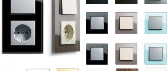
Types of distribution boards
When changing or repairing electrical wiring in an apartment, the central link is the distribution panel. When choosing a distribution panel for an apartment, you need to understand that the panels can be mounted or built-in.
The hinged panel is installed on the wall. To install it, you do not need to carry out dirty and noisy work on the wall, which in some cases is a definite plus. The appearance of the hinged panel resembles a small cabinet. Modern hinged panels have a pretty good aesthetic appearance and despite the fact that the hinged panel takes up a lot of space on the wall, they are very often installed when replacing and repairing the electrical wiring of an apartment.
Conclusions based on the results of the work done
Now it makes no sense to talk about the amount of my financial expenses. Any costs always depend on the quality of the product, the manufacturer of the automatic protection elements and other parts required for assembly. I can only say one thing: the savings on specialist labor costs amounted to about 10,000 rubles. The whole job (I had no such experience) took a total of about 5 hours. Again, the amount saved can be many times greater. It largely depends on the region, average prices and salaries in the city. However, even saving a small amount is worth doing all the work yourself. And experience will never be superfluous.
The editors of Homius.ru invite home craftsmen and craftsmen to become co-authors of the “Stories” section. Useful first-person stories will not only be published on the pages of our online magazine, its authors will receive a small financial reward.
Next STORIES How I built a barbecue gazebo with my own hands: the experience of a Homius reader
Selecting a wall-mounted distribution panel
A mounted distribution board is selected according to the number of planned circuit breakers corresponding to the power supply groups in the apartment. Panels differ in the number of protection and control devices that can be installed in the panel. They are called modules.
Note: The module is a place in the panel for installing one single-pole circuit breaker. Accordingly, an RCD (residual current device) requires two modules, and a three-pole circuit breaker requires three modules.
If you have an electrical project for an apartment, then the type of panel can be viewed on a sheet with a single-line design diagram. Without a project, the master must tell you the number of modules in the panel. He must draw a diagram of the panel, on which the necessary protection and control modules of the electrical network will be visible. If you are doing the repairs yourself, then independently calculate the number of groups in the apartment (Read the article: Calculation of cable cross-sections, circuit breakers). Determine how many RCDs (residual current devices) are needed and determine the required number of protection and control modules in the panel.
Mounted panels are available with an even number of modules, starting from 6 pieces. A hinged panel with minimal space for modules is called a mini panel or mini box. Shields can be arranged with circuit breakers in one, two, three or four rows.
The configuration of the shields varies and depends on the manufacturer. Typically, the kit includes fasteners, DIN rails for installing circuit breakers (modular devices) and connecting blocks for connecting wires.
Note: A DIN rail is a metal plate with a special curved profile for convenient and quick installation of circuit breakers on it.
Mounted panels can be with or without a special place for the metering meter. With space for a meter or an already installed meter, hinged panels are called metering and distribution panels.
Also, hinged panels have either metal or plastic housings.
The degree of protection of the apartment panel must be at least IP31 (PUE 7.1.28, Link at the bottom of the article).
Note: IP is the degree of protection of an electrical device in accordance with the accepted international standard IEC 60529 (German: DIN 40050, Union: GOST 14254-96) shows under what external influences the device can operate properly. The maximum protection is IP 68, the minimum IP 22. For example, the incoming power supply device at home, for installation outdoors, must have a protection degree of at least IP 55. (You can read the article about the Input Device here)
Note! Installation of electrical wiring in a one-room apartment
Simultaneously with the selection of the hinged shield, you need to select a place for its installation.
Conclusions and useful video on the topic
Video #1. Electrical panel assembly option:
Video #2. Assembly instructions and recommendations for a 72-module panel:
You can assemble the electrical panel yourself, but checking the installation and connection by a qualified electrician is mandatory. Without an appropriate conclusion, the organization supplying the house with electricity will simply block the line.
Would you like to talk about your own experience in electrical installation work? Do you have useful information that could be useful to independent novice electricians? Please write comments in the block below, post photos and ask questions about the topic of the article.
Place for installing a wall-mounted distribution panel
When choosing a location for installing a mounted distribution panel, I would recommend basing it on the PUE standards (Electrical Installation Rules chapter 7.p.7.1.28,35,36)
- The distance from the hinged panel to any pipeline in the apartment, including water supply, sewerage, heating pipes, must be at least 1 meter.
- The shield must be installed in a place convenient for maintenance.
- The height from the floor is recommended 1.5-1.6 meters to the meter window. If the panel is without a meter, the installation height is regulated only by ease of maintenance, usually 1.5-1.7 meters. True, when fighting for space, some install a hinged panel under the ceiling.
By the way, according to old standards, distribution panels with fuses were installed at a height of two meters from the floor. This is due to the provision of electrical safety measures. since these distribution panels did not have any external protection, but looked like an open panel with fixed fuses, “plugs”.
After choosing a place to install the mounted distribution panel, purchasing it and completing it, you can begin installation.
Preparing tools
Installation of the shield is not complete without power tools. The wires in the walls are laid in grooves, to form which they take a wall chaser or a grinder with a circle on the stone. Small volumes are made with a chisel and hammer.
The cabinet is attached to a concrete or brick wall with dowels, so you will need a hammer drill and drills with pobedit tips. On wooden surfaces, a drill is used, and the screws are tightened with a screwdriver.
Electrician's special tools:
- soldering iron, screwdriver sets;
- probe screwdriver;
- portable welding;
- pliers, side cutters;
- current clamps.
A multimeter is needed to determine the electrical parameters of the network and individual devices. They measure electric current, DC and AC voltage, and resistance. A multimeter is used to test fuses, input devices and other devices.
Installation height of the shield in the apartment
This article provides rules and advice for connecting distribution boards based on the standards of the Republic of Belarus and Russia, and recommendations from the world's leading manufacturers of panel board products.
The electrical panel is the heart of your electrical installation. It is designed to house the devices and equipment needed to distribute all electrical circuits and protect people and property.
Selecting an electrical panel
Parameters for selecting a distribution board:
1. Type of installation. There are internal versions, for hollow or hollow walls (plasterboard) and external versions (attached to any base).
When choosing the type of electrical panel, pay attention to the material and design features of the walls of the room in which it will be installed. For example, in panel houses, it is practically impossible to install a built-in electrical panel of more than 12 modules without causing damage to the load-bearing walls. In such rooms, it is recommended to install panels either externally or internally for hollow walls, with a plasterboard structure.
2. Number of modules . For apartments and cottages, switchboards are used with the ability to install modular devices up to 63A. The number of modules determines the total number of electrical wiring lines and modular devices + a reserve of at least 20% (preferably 30%) is made for the possible connection of additional equipment in the future.
3. Degree of protection. For indoor installation, electrical panels with a degree of protection of IP30-IP40 are used, and for installation in unfavorable conditions (basement, bathhouse, open area), you should choose panels with a degree of protection IP44-IP65.
4. Material. Shields can be made of metal or plastic. In residential premises, it is better to opt for plastic panels, and in utility rooms (garage, workshop, etc.) it is better to use metal ones.
Electrical panels located in residential premises must have lockable doors (preferably metal ones). If there are children, the door must be closed with a locking device that does not allow a child to open it. Locking the apartment panel with a key is not recommended.
Electrical panel placement
For the input device for power supply and telecommunications, in residential premises it is recommended to provide areas in which the installation of an electrical panel, fire alarm and security systems, automation equipment, telecommunication networks (telephone, television, Internet, etc.) is carried out.
Centralizing various devices in one place allows for easier access and maintenance of various components necessary for the normal functioning of electrical equipment and low-current systems located in the same room.
Such zones should be located in the apartment itself or in the house (preferably at the entrance), in the garage or in an additional room (panel room).
Electrical panels can be installed both in specially prepared niches (internal installation) and on various fire-resistant bases (outdoor installation).
The shield is installed at a height ranging from 1 meter (lower edge) to 1.8 meters (upper edge). As an exception, the shield can be installed within 0.5 - 1.3 meters if elderly people or people with disabilities live in the room.
Installation of distribution boards (for an apartment or private house) is prohibited :
- In bathrooms and showers (outside and in hazardous areas 0, 1 and 2);
- In a closet or wardrobe;
- Above heaters;
- Under and above the sink or washbasin;
- Above the hob;
- Installation outside the home (including balcony or loggia)*
- In the toilet;
- On flights of stairs;
- In damp areas;
- In ventilation shafts;
*The distribution board should not be confused with the metering board, which can be installed at the border of a country house plot.
Selecting the cable cross-section for powering the electrical panel
The cross-section of the cable cores supplying the internal distribution board (apartment or house) depends on:
1. Voltage rating (220 or 380 Volts).
The electrical panel of the apartment in most cases is connected to a single-phase voltage of 220-230 Volts. Three-phase input, in apartments in Minsk, is very rare and practically never occurs.
In country houses, the best solution would be to connect to a three-phase voltage - 380-400 Volts.
2. The allocated power and rating of the main feeding machine (installed in a common floor switchboard or in a metering switchboard), as well as the distance between switchboards.
If the distance between the main supply circuit breakers (or switches) of the panels is no more than 30 meters, then the cable cross-section for single-phase power supply of the apartment panel can be determined from the table below:
If the distance between the main power supply circuit breakers (or switches) of the panels is more than 30 meters, then when choosing the cross-section of the cable cores, it should be additionally determined using tables (taking into account power and distance).
To quickly select the desired cable cross-section, taking into account the distance, the following table will help:
Which cable to choose?
To power the apartment panel, it is better to use a flame retardant cable (VVGngLS). To power a switchboard in a country house, you should use an armored cable laid in the ground (VBbShv or AVBbShv).
To switch wires inside the switchboard, single-wire wires PuV (formerly PV1) and multi-core wires PuGV (formerly PV3, PV4) should be used. PuV and PuGV are ideal for use when installing modular equipment in a switchboard. They do not propagate combustion, are resistant to environmental influences (within the temperature range: from -50 o C to +70 o C), the service life is at least 15 years.
Stranded wire (PugV), before connecting, should be crimped with special lugs (NShvI, etc.)
What cross-section of wire should I use when assembling the panel?
To connect power equipment in a distribution board (circuit breakers, differential protection), there is a European standard that requires the use of a certain wire cross-section, depending on the maximum current of the devices. This:
- 10mm 2 for maximum current 45A;
- 16mm 2 for maximum current 60A;
- 25mm 2 for maximum current 90A;
In practice, as a rule, it is used:
- 6-10mm 2 for maximum current 40;
- 10-16mm 2 for maximum current 63A;
Standards and regulations
Standards, rules and recommendations for the installation of electrical equipment and modular equipment in electrical panels:
- Each switchboard must have a technical passport, which must indicate the following data: name of the manufacturer and its trademark, mark of conformity, type designation, rated current of the shield, voltage and frequency, degree of protection, technical specifications, year of manufacture
- It is prohibited to lay cables or connecting lines under the Din-rail
- Recommended clamp tightening torque 2 - 3.5 Nm
- The metal body of the switchboard must be grounded
- The cable supply for connecting lines should be 1.5-2 times the height of the connected shield (but not less than 400mm) in length.
- The lines in the electrical panel and the installed equipment must be marked and their meaning indicated (for example, using stickers located below the equipment or in a table located on the inner door of the panel)
Let's discuss this article together:
Click to cancel reply.
What elements does the electrical panel consist of?
Most often, the switchboard contains such components.
- VA. An input circuit breaker (or VA) is installed to protect the wiring loop. The main incoming conductor is connected to the VA terminals. Often, for convenience and comfortable use, a switch is installed in front of this device. Its installation is also rational because it makes it easy to de-energize the circuit going into the apartment in order, for example, to replace failed elements in the electrical panel.
- Electricity meter. This device comes only after VA. Its function is to calculate the energy consumed. Many people install an electric meter outside the switchboard along with the VA. For example, this could be a platform or vestibule of an apartment building.
- RCD. This element is necessary to prevent fire or electric shock. It can be one in the circuit (attached after the meter) or several of them are installed on each line where large energy consumption is expected (air conditioner, water heater, electric stove, etc.).
- Linear machine. Connecting the machine in the apartment panel is necessary to control individual lines (lighting or household appliances). Their function is to break the electrical circuit when a short circuit or overload occurs. Thus, they keep wiring and energy-consuming devices intact.
- Difavtomat. This device replaces the RCD and the machine combined. Its use is advisable if space in the shield is limited.
- Busbars for connection. These elements are needed to connect working grounding and neutral conductors.
- RackDIN. Necessary for mounting devices in the electrical panel. Not a single machine circuit in an apartment panel can do without this element.
- Tires for distribution. This part is needed for linking automatic devices, automatic devices and RCDs. It can be a working zero, or as a current conductor.
To connect a three-phase outlet, the number of elements used in the electrical panel is no different from a single-phase one. True, they use components suitable for this type of network.
Is an RCD necessary?
Many people ask whether it is necessary to spend money on installing an RCD. This is required for safety reasons. The task of such devices is to compare the currents at the input and output, detect leakage and turn off the power if a large difference appears.
The point is simple. In normal mode, the current indicators at the input and output do not differ. If a person comes under voltage or another leak occurs, a difference appears in the RCD. This is enough for instant shutdown.
For power lines and outlets, it is recommended to select a 30 mA device. In this case, the rated current should be the same as that of the AB.
If we are talking about a room with high humidity, it is better to take an RCD with a current of 10 mA.
The device can be placed on one line or group. As an alternative, you can install a difavtomat, which combines the options AB and RCD.
Electricity metering
7.1.59. In residential buildings, one single- or three-phase billing meter (with three-phase input) should be installed for each apartment.
7.1.60. Calculation meters in public buildings that house several electricity consumers must be provided for each consumer, isolated in administrative and economic terms (studio, shops, workshops, warehouses, housing maintenance offices, etc.).
7.1.61. In public buildings, estimated electricity meters must be installed on the ASU (main switchboard) at the points of balance demarcation with the energy supply organization. If there are built-in or attached transformer substations, the power of which is fully used by consumers of a given building, the calculated meters should be installed at the low-voltage terminals of power transformers on combined low-voltage switchboards, which are also the building’s ASU.
ASU and metering devices for different subscribers located in the same building may be installed in one common room. By agreement with the energy supplying organization, settlement meters can be installed at one of the consumers, from which the ASU supplies other consumers located in the building. At the same time, control meters should be installed at the inputs of the supply lines in the premises of these other consumers for settlements with the main subscriber.
7.1.62. Estimated meters for the general house load of residential buildings (lighting of staircases, building management offices, yard lighting, etc.) are recommended to be installed in ASU cabinets or on main switchboard panels.
7.1.63. It is recommended to place residential meters together with protection devices (circuit breakers, fuses).
When installing apartment panels in the hallways of apartments, meters, as a rule, should be installed on these panels; installation of meters on floor panels is allowed.
7.1.64. To safely replace a meter directly connected to the network, a switching device must be provided in front of each meter to remove voltage from all phases connected to the meter.
Disconnecting devices for removing voltage from settlement meters located in apartments must be located outside the apartment.
7.1.65. After the meter connected directly to the network, a protection device must be installed. If several lines equipped with protection devices extend after the meter, installation of a common protection device is not required.
7.1.66. It is recommended to equip residential buildings with remote meter reading systems.