In process automation, it is very often necessary to take indicators of temperature changes in order to load them into control systems for the purpose of further processing. This requires high-precision, low-inertia sensors that can withstand high temperature loads within a certain measurement range. Thermocouples are widely used as thermoelectric converters - differential devices that convert thermal energy into electrical energy.
The devices are also a simple and convenient temperature sensor for a thermoelectric thermometer designed to make accurate measurements over fairly wide temperature ranges. In particular, the control automation of gas boilers and other heating systems is triggered by an electrical signal coming from a thermocouple-based sensor. The sensor designs provide the necessary measurement accuracy in the selected temperature range.
Thermocouple device
The principle of operation of a thermocouple. Seebeck effect
The operation of a thermocouple is due to the occurrence of the thermoelectric effect, discovered by the German physicist Thomas Seebeck in 1821.
The phenomenon is based on the occurrence of electricity in a closed electrical circuit when exposed to a certain ambient temperature. An electric current occurs when there is a temperature difference between two conductors (thermoelectrodes) of different compositions (dissimilar metals or alloys) and is maintained by maintaining the location of their contacts (junctions). The device displays the measured temperature value on the screen of the connected secondary device.
The output voltage and temperature are linearly related. This means that an increase in the measured temperature results in a higher millivolt value at the free ends of the thermocouple.
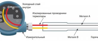
The junction located at the temperature measurement point is called the “hot” junction, and the place where the wires are connected to the converter is called the “cold” junction.
Cold junction temperature compensation (CJT)
Cold junction compensation (CJC) is compensation introduced in the form of a correction to the final readings when measuring the temperature at the point of connection of the free ends of the thermocouple. This is due to discrepancies between the actual temperature of the cold ends and the calculated readings from the calibration table for the cold junction temperature at 0°C.
CHS is a differential method in which the absolute temperature readings are obtained from the known value of the cold junction temperature (another name is the reference junction).
Thermocouple design
When designing a thermocouple, the influence of such factors as the “aggressiveness” of the external environment, the state of aggregation of the substance, the range of measured temperatures, and others are taken into account.
Thermocouple design features:
1) The junctions of the conductors are connected to each other by twisting or twisting with further electric arc welding (rarely soldering).
2) Thermoelectrodes must be electrically insulated along their entire length, except the point of contact.
3) The insulation method is selected taking into account the upper temperature limit.
- Up to 100-120°C – any insulation;
- Up to 1300°C – porcelain tubes or beads;
- Up to 1950°C – tubes made of Al2O3;
- Above 2000°C – tubes made of MgO, BeO, ThO2, ZrO2.
4) Protective cover.
The material must be thermally and chemically resistant, with good thermal conductivity (metal, ceramics). Using a cover prevents corrosion in certain environments.
Extension (compensation) wires
This type of wire is necessary to extend the ends of the thermocouple to a secondary device or barrier. Wires are not used if the thermocouple has a built-in converter with a unified output signal. The most widely used standardizing converter is located in the standard terminal head of the sensor with a unified 4-20mA signal, the so-called “pill”.
The material of the wires may be the same as the material of the thermoelectrodes, but most often it is replaced with a cheaper one, taking into account the conditions that prevent the formation of parasitic (induced) thermo-EMF. The use of extension wires also allows for optimization of production.
ARIES DTPHxx4 Thermoelectric converters based on KTMS with cable output.
Example of designation when ordering: OWEN DTPN444-09.100/5S.1 This means that a “nichrosil-nisil” thermocouple with a temperature measurement range: -40...+1250 °C, with an insulated working junction, with a diameter of KTMS 4.5 is subject to production and delivery mm, mounting part length 100 mm, silicone cable outlet length 5 m, tolerance class 1, design 444.
Example of designation when ordering: OWEN DTPC264-07.100/5000/10С.1 This means that a thermoelectric converter with a sensitive element K, fitting material 12Х18Н10Т, protective shell material KTMS - AISI321, with a temperature measurement range: -40... + is subject to production and delivery 800°C, with an insulated working junction, diameter MLC 3 mm, length of mounting part L1=100 mm, lead length MLC L2=5000 mm, length of silicone cable lead 10 m; design 264.
Features of the use of the most common thermocouples
Technical characteristics depend directly on the materials from which they are made.
Type J (Iron Constantan Thermocouple)
- It is not recommended to use below 0°C, because Moisture condensation on the iron terminal leads to the formation of rust.
- The most suitable type for rarefied atmospheres.
- The maximum temperature of use is 500°C, because Above this temperature, rapid oxidation of the leads occurs. Both terminals are quickly destroyed in a sulfur atmosphere.
- The readings increase after thermal aging.
- Low cost is also an advantage.
Type E (chromel-constantan thermocouple)
- The advantage is high sensitivity.
- Thermoelectric homogeneity of electrode materials.
- Suitable for use at low temperatures.
Type T (copper-constantan thermocouple)
- Can be used below 0°C.
- Can be used in atmospheres with slight excess or deficiency of oxygen.
- Use at temperatures above 400°C is not recommended.
- Not sensitive to high humidity.
- Both leads can be annealed to remove materials causing thermoelectric inhomogeneity.
Type T thermocouples.
Type K (chromel-alumel thermocouple)
- Widely used in various areas from -100°C to +1000°C (recommended limit depending on the diameter of the thermoelectrode).
- In the range from 200 to 500°C, a hysteresis effect occurs, i.e., readings during heating and cooling may differ. Sometimes the difference reaches 5°C.
- Used in a neutral atmosphere or an atmosphere with excess oxygen.
- After thermal aging, the readings decrease.
- It is not recommended to use in a rarefied atmosphere, because... chromium can be released from the Ni-Cr terminal (so-called migration), and the thermocouple changes the thermoelectric force and shows a low temperature.
- A sulfur atmosphere is harmful to a thermocouple because affects both electrodes.
Type K thermocouple.
Type N (nicrosil-nisil thermocouple)
- This is a relatively new type of thermocouple, developed from the K-type thermocouple. The K-type thermocouple can be easily contaminated by impurities at high temperatures. By fusing both electrodes with silicon, the thermocouple can be precontaminated and thus reduce the risk of further contamination during operation.
- Recommended operating temperature up to 1200°C (depending on wire diameter).
- Short-term operation is possible at 1250°C.
- High stability at temperatures from 200 to 500°C (significantly less hysteresis than for a type K thermocouple).
- Considered to be the most accurate base metal thermocouple.
Type N thermocouple.
General Tips for Selecting Base Metal Thermocouples
- Application temperature below zero – type E, T
- Room temperatures for use – type K, E, T
- Application temperature up to 300°C – type K
- Application temperature from 300 to 600°C – type N
- Application temperature above 600°C – type K or N
Precious metal thermocouples
Recommended maximum operating temperature 1350°C. Short-term use is possible at 1600°C. It becomes contaminated at temperatures above 900°C with hydrogen, carbon, and metallic impurities of copper and iron. When the iron content in the platinum electrode is 0.1%, TEMF changes by more than 1 mV (100°C) at 1200°C and 1.5 mV (160°C) at 1600°C. The same picture is observed with copper contamination. Thus, thermocouples should not be reinforced with steel tube, or the electrodes should be insulated from the tube with gas-tight ceramics. Can be used in oxidizing atmosphere. At temperatures above 1000°C, the thermocouple may become contaminated with silicon, which is present in some types of protective ceramic materials
It is important to use ceramic tubes consisting of high purity aluminum oxide. It is not recommended to use below 400°C, since the thermoelectric force in this region is small and extremely nonlinear.
Precious metal thermocouples
Type B (platinum-platinum-rhodium)
Recommended maximum operating temperature is 1500°C (depending on wire diameter). Short-term use is possible up to 1750°C. Can be contaminated at temperatures above 900°C by hydrogen, silicon, copper and iron vapor, but the effect is less than for S and R thermocouples. At temperatures above 1000°C the thermocouple can be contaminated by silicon, which is present in some types of protective ceramic materials
It is important to use ceramic tubes consisting of high purity aluminum oxide. Can be used in oxidizing environments. Application is not recommended at temperatures below 600°C, where the emf is very small and nonlinear.
Chromel-copel type L
It is also a commonly used thermocouple allowing measurements in inert and oxidizing environments.
Long-term measurement up to 800 0С, short-term – 1100 0С. The lower limit is -253 0C. Long-term operation up to 600C. This is the most sensitive thermocouple of all industrial-type measuring devices. Has linear graduation. At a temperature of 600 degrees it is distinguished by thermoelectric stability. The disadvantage is the increased susceptibility of the electrodes to deformation. The positive electrode of a type L thermocouple is chromel, and the negative electrode is kopel. The working medium is oxidizing or with an inert gas component. Can be used in vacuum at elevated temperatures for a short time. Using good gas-tight protection, THC can be used in sulfur-containing and oxidizing environments. Operation in a chlorine or fluorine-containing atmosphere is possible, but only up to 200 degrees.
Design and principle of operation
It is known that in a closed circuit, which consists of two conductors of different metals (for example, chromel and copel), a thermoelectromotive force (EMF) arises, provided that their hot and cold junctions have different temperatures (Seebeck effect). The value of the EMF depends on the materials of the conductors, the temperatures of their cold and hot junctions.
Typically, the voltage of a household thermocouple is in the range of 20-60 millivolts (mV), which is enough to open the gas valve, but, of course, not enough to operate complex automation and other modules that already require an electrical connection.
This is what a standard thermocouple looks like in the photo.
The module is not limited to a pair of junctions, but the thermocouple device is quite simple and understandable:
- The sleeve, inside of which there are thermoelectrodes with the “hot” junction of the conductors, is what is attached to the burner module of the boiler, next to the pilot burner (igniter).
- An extension cord, protected by a copper tube from external influence of electromagnetic fields, is used to connect the working part (hot junction) with the electromagnetic gas valve.
- A dielectric washer with a “cold” junction, it is this that is inserted into the socket of the gas solenoid valve.
Most often, thermocouples of domestic gas boilers use junctions made of chromel and alumel (TCA), chromel and copel (TCC), and iron and constantan (TLC). All alloys used, their markings and characteristics are listed in the table below.
| Thermocouple type (European classification) | Junction conductor materials | Russian markings | Temperature range, °C |
| K | chromel-alumel | THA | -200 – 1 300 |
| L | chromel-copel | THC | -200 – 850 |
| J | iron-constantan | TZHK | -100 – 1 200 |
| N | nikhrosil-nisil | TNN | -200 – 1 300 |
| T | copper-constantan | TMKn | -200 – 400 |
| E | chromel-constantan | THKn | 0 – 600 |
| S | platinum-rhodium-platinum | TPP10 | 0 – 1 700 |
How does a thermoelectric thermometer work as part of a gas boiler?
The operating principle of a thermocouple in a gas boiler is the same everywhere:
- First, a person mechanically opens the gas supply valve by holding the solenoid valve button for 15-30 seconds.
- Then the piezo ignition button is pressed once, a spark appears and the pilot burner lights up.
- The magnetic valve button is held down for another 30-60 seconds until the working junction of the thermocouple, located next to the igniter, heats up and produces the required voltage.
- After 30-60 seconds, the solenoid valve button is released, but combustion continues as the heated thermocouple produces enough voltage to hold the gas valve open. The boiler operates normally, without human intervention.
- Once combustion stops, the flame no longer heats the thermocouple, causing the voltage to be insufficient to hold the gas solenoid valve open and it closes, stopping the flow of gas.
ARIES DTPHxx1 Thermoelectric surface converters.
Example of designation when ordering: ARIES DTPL021-0.5/5 This means that a Chromel-Kopel thermoelectric converter, model 021, with insulation - MKRTs tube, thermoelectrode diameter 0.5 mm, thermocouple length 5 m, range measurements: -40…+600 ⁰С.
Example of designation when ordering: OWEN DTPC031-0.7/10/3 This means that the thermoelectric converter “chromel-alumel”, model 031, with insulation – MKRTs tube, thermoelectrode diameter 0.7 mm, thermocouple length – 10, is subject to production and delivery m, cable outlet length – 3 m, measurement range: -40…+1100 ⁰С.
The design and principle of operation of a thermocouple
Indeed, not every material can be constantly in the open flame zone. The thermoelement is made of metal, or rather, of several metals, so it is not afraid of high temperatures. When operating a gas boiler installation, there is no way to do without it; failure of the thermocouple means a complete shutdown of the unit and immediate repairs. The thing is that the thermoelement works in conjunction with an electromagnetic shut-off valve that closes the entrance to the fuel path. As soon as this part fails, the valve will close, the fuel supply will stop and the burner device will go out.
To better understand the principle of operation of a gas boiler thermocouple, it is worth considering the diagram presented in the figure.
Thermocouple circuit
This principle is based on the following physical phenomenon: if you reliably connect 2 dissimilar metals together, and then heat the junction, then a potential difference, that is, voltage, will appear at the cold ends of this junction. And when a measuring device is connected to them, the circuit will close and a direct electric current will arise. The voltage will be very small, but this is quite enough for induction to occur in the sensitive coil of the solenoid valve and it to open, allowing fuel to pass to the igniter.
For reference. Some modern solenoid valves are so sensitive that they remain open until the input voltage drops below 20 mV. The thermocouple in normal operating mode produces a voltage of about 40-50 mV.
Accordingly, the device of a gas boiler thermocouple is based on the described phenomenon, called the Seebeck effect. Two parts made of different metals are firmly connected to each other at one or more points, and the quality of the connection plays a big role. It affects the operating parameters of the element and the durability of its operation. The connection point will be the very working part placed in the open fire zone.
Since many different pairs of metals are used for the manufacture of thermoelements, without going into details, we note that the thermocouple for a gas boiler uses a chromel - aluminum pair. Conductors enclosed in a protective sheath are welded to the cold ends of these metals. The second end of the conductors is inserted into the corresponding socket of the unit automation and secured with a clamping nut.
In the process of igniting the igniter and burner of a gas boiler to supply fuel, we open the solenoid valve manually by pressing its rod. The gas enters the igniter and is ignited, and the thermocouple is located nearby and is heated by its flame. After 10-30 seconds, the button can be released, since the thermoelement has already begun to generate voltage that keeps the valve stem open.
Thermocouple operating principle of resistance thermal converter TSPT (TSMT)
Resistance thermal converters TSPT (TSMT) with a two-wire connection circuit are manufactured only with tolerance class B or C and have restrictions on installation lengths and lengths of extension wires. In accordance with the requirements of GOST 6651-2009, for sensors with a two-wire connection circuit, the resistance of the internal wires should not exceed 0.1% of the nominal resistance of the vehicle at 0°C. In this regard, for various NSH there are restrictions on installation lengths:
– for sensors with a terminal head, the maximum installation length is Lmax= (500÷1250) mm, depending on the design modification, – for sensors with an extension wire, the maximum wire length is ℓ max= (500÷1000) mm, depending on the design modification.
Sensors with a three- and four-wire connection scheme, depending on design modifications, are manufactured according to tolerance classes AA, A, B, C. There are no restrictions on installation lengths and lengths of extension wires during manufacturing. It should be taken into account that the secondary devices to which the sensors are connected may have limitations on the input resistance of the measuring line, which in turn depends on the length of the sensor wire.
Table 1. Nominal resistance R0
| Designation of vehicle version | Pt | P | M |
| Temperature coefficient a, °С-1 | 0,00385 | 0,00391 | 0,00428 |
| Nominal resistance R, Ohm | 100, 500; 1000 | 50, 100 | 50, 100 |
Measurement uncertainty of resistance thermometers
A resistance thermal converter can be recognized as acceptable by the manufacturer (or a calibration center) if the deviation of the vehicle resistance from NSX, taking into account the expanded uncertainty of measurement in the manufacturer’s or verifier’s laboratory, calculated in the temperature equivalent (R–Rinx ± Upr)/(dR/dt), is within tolerance interval ±Δt (see TS No. 1 in Fig. 3).
A resistance thermal converter can be rejected by the consumer only if the deviation of the resistance of the vehicle from NSX, taking into account the expanded measurement uncertainty under the conditions of use of the thermometer by the consumer, calculated in the temperature equivalent (R–Rinx ± Uin)/(dR/dt), is completely outside the interval tolerance ±Δt.
This acceptance rule, on the one hand, reduces the risk of a consumer who may purchase a low-quality resistance thermometer only due to large measurement errors in production; on the other hand, this rule encourages the manufacturer to use high-precision measuring equipment when accepting thermometers. The rule is also very important when establishing a defect by the Customer, since the Customer is also obliged to assess the uncertainty of his measurements and only after that make claims to the manufacturer.
The scope and sequence of primary and periodic vehicle verifications are established in accordance with GOST R 8.624, while the list of mandatory controlled parameters is the same. Primary verification, carried out by the accredited metrological service of our enterprise, is combined with acceptance tests.
The uncertainty of temperature measurement results with thermocouples and resistance thermometers is influenced by many factors, the main ones being:
– random effects during measurement; – measurement uncertainty of the recording device; – tolerance class of thermocouple or resistance thermometer; – change in the characteristics of the TP or TS during the interverification interval (MPI); – for TP, additionally, the accuracy class of the extension wires connecting the thermocouple to the recording device and the error of temperature compensation of the reference junctions;
Characteristics of sources of uncertainty in temperature measurement by a thermoelectric converter are presented in Table 3. The uncertainty budget is compiled in accordance with the Guide to the Expression of Uncertainty and regulatory documents.
The contribution of random effects, instability characteristics of the measured temperature and thermal contact with the medium were not taken into account in the calculations, based on the fact that these values depend on the conditions of use.
The choice of measuring current also affects the accuracy of temperature measurement. Since the SE is made of very thin wire or film, even a small current can cause significant heating of the SE. To avoid a significant increase in error due to heating of the SE by the measuring current, for 100-ohm vehicles it is recommended to use currents of 1 mA and lower. In this case, the error will not exceed 0.1 °C. To reduce the heating effect of the SE, a pulsed measuring current is sometimes used.
Stamps
The products are made from thermoelectrode nickel alloy Chromel NX 9.5 and copper-nickel alloy Kopel MNMts 43-0.5.
Nickel (Ni) is the basis of chromel. Its content is 87.4-90.4% (includes 0.6-1.2% cobalt (Co)). Chromium (Cr) is represented by 9-10%, the remaining elements, which include manganese (Mn), silicon (Si), iron (Fe) and some others make up tenths, hundredths and thousandths of a percent.
Copel, in addition to nickel and cobalt (Ni+Co) - 42.5-44.0%, contains 54.4-57.4% copper (Cu). These two elements form its basis. Among the remaining components of the material, manganese (Mn) can be distinguished, the mass fraction of which is 0.1-1%.
The chemical composition of the NH 9.5 and MNMts 43-0.5 grades is presented in the GOST 492-2006 standard and is regulated by it.
Related topics:
Thermocouple (thermoelectric temperature transducer) is a thermoelement used in
measuring and converting devices, as well as in automation systems.
The international standard for thermocouples IEC60584 (clause 2.2) gives the following definition of a thermocouple:
Thermocouple - a pair of conductors made of different materials connected at one end and forming
part of a device that uses the thermoelectric effect to measure temperature.
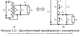
To measure the temperature difference between zones, one of which does not contain a secondary converter
(thermo-EMF meter), it is convenient to use a differential thermocouple: two identical thermocouples,
connected towards each other. Each of them measures the temperature difference between its worker
solder with a conventional junction formed by the ends of thermocouples connected to the terminals of the secondary
converter, but the secondary converter measures the difference. their signals are thus two
thermocouples together measure the temperature difference between their working junctions.
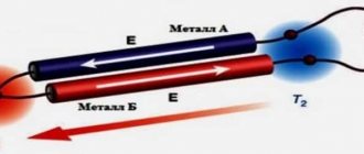
The operating principle is based on the Seebeck effect or, in other words, the thermoelectric effect.
When the ends of the conductor are at different temperatures, a potential difference arises between them, proportional to the temperature difference. The proportionality coefficient is called the thermopower coefficient. Different metals have different thermopower coefficients and, accordingly, the potential difference arising between the ends of different conductors will be different. By placing a junction made of metals with excellent thermoelectric coefficients in a medium with a temperature T1, we will obtain a voltage between opposite contacts located at a different temperature T2, which will be proportional to the difference in temperatures T1 and T2.
Measurement speed
The performance is determined by the ability of the primary converter to quickly respond to temperature surges and the subsequent flow of input signals from the measuring device.
Factors that increase performance:
- Correct installation and calculation of the length of the primary converter;
- When using a converter with a protective sleeve, it is necessary to reduce the mass of the assembly by selecting a smaller diameter of the sleeves;
- Minimizing the air gap between the primary converter and the protective sleeve;
- Using a spring-loaded primary converter and filling the voids in the sleeve with a heat-conducting filler;
- A fast moving or denser medium (liquid).
Principle of operation
The thermocouple, whose operating principle is based on the effect discovered by T. Seebeck in 1822, is a purely differential sensor.
This principle is as follows: in a closed circuit of two conductors of different types, if there is a temperature gradient between the junctions, an electric current appears. Thermocouples create an electrical signal that is proportional to the temperature difference between two different points. Thus, the junction used to measure the required temperature is called the “hot” junction, and the other junction is called the “cold” junction.
Typically, the temperature being measured is higher than the temperature at which the measuring device is located. Difficulties in using pairs relate to the use of cold junction voltage. Basically, what is required is to measure the temperature at a specific point, rather than the difference in temperature between two points, which is what a thermocouple does.
Principle of operation
The operation of any thermocouple is based on the thermoelectric effect, which was discovered by T.I. Seebeck back in 1821. This effect lies in the fact that if two dissimilar metal conductors are connected in series with each other, thus forming a closed electrical circuit, and heating is applied at one junction of the conductors, then an electromotive force (EMF) appears in the circuit. This electromotive force is called thermo-emf. Under the influence of thermo-EMF, an electric current begins to flow in a closed circuit.
How does a thermocouple work?
The heating point is usually called the hot junction. A place where there is no heating is a cold junction. If you connect a galvanometer or microvoltmeter to the open circuit, you can measure the value of the thermo-EMF, which will be several milli- or microvolts. The value of thermo-EMF will depend on the amount of heating at the junction of the conductors and on the temperature at the junction of the conductors, where heating does not occur. Those. the value of thermo-emf depends on the temperature difference between the cold and hot junction. Also, thermo-EMF depends on the type of conductors themselves.
Thus, if the junction of dissimilar conductors of a thermocouple is heated, then a potential difference will arise between the unconnected (free) ends of the conductors, which can be measured with an electrical measuring instrument. Thanks to modern converters, the resulting potential difference can be converted into a specific digital value, i.e. it is quite possible to find out the value of the heating temperature at the junction of the thermocouple conductors. For accurate measurements, the cold junction temperature must remain constant. Because This is not always possible; special compensation circuits are used to compensate for the temperature of the cold junction.
Thermocouple device.
Device design
Modern thermocouples are manufactured in various shapes and lengths. According to their design, they can be divided into two groups:
- open-frame thermocouples;
- thermocouples with a protective casing.
The first are a product in which the junction of two conductors is not closed and not protected from external influences. This design allows for fast temperature measurement times and low inertia. The second type of thermocouple is available in the form of a probe. The probe is a metal tube with an internal insulator that can withstand high temperatures. A thermoelectric thermocouple element is placed inside the probe. Thanks to this design, the thermoelement is protected from the influence of aggressive environments of various technological processes.
Type J thermocouple.
Cold junction
The cold junction is often the point where the free ends of the thermocouple wires are connected to the meter. Since the thermocouple circuit meter is actually measuring the voltage difference between the two junctions, the cold junction voltage must be kept as constant as possible. By maintaining the voltage at the cold junction at a constant level, we thereby ensure that a deviation in the readings of the measuring device indicates a change in the temperature at the working junction.
If the temperature around the cold junction changes, the voltage across the cold junction will also change. As a result, the voltage at the cold junction will change. And as a result, the difference in voltage at the two junctions will also change, which will ultimately lead to inaccurate temperature readings. In order to keep the cold junction temperature constant, many thermocouples use compensating resistors. The resistor is in the same location as the cold junction, so the temperature affects the junction and the resistor at the same time.
Gas stove thermocouple.
Working junction of thermocouple (hot)
A service junction is a junction that is exposed to the process whose temperature is being measured. Due to the fact that the voltage generated by a thermocouple is directly proportional to its temperature, when the working junction is heated, it generates more voltage, and when cooled, less.
What does a thermocouple consist of?
Working principle of thermocouple
A thermoelectric converter consists of two conductors (A and B), which are made of different metals (alloys). They are combined into a single electrical circuit. The connection points (t1 and t2) are placed in zones with different temperatures. This action initiates the generation of electromotive force (current).
Diagram explaining the principle of operation of a thermocouple
Notes:
- A (B) – positive (negative) electrode, respectively;
- t1 – “hot junction”, which is installed in an area with high temperature;
- t2 – “cold junction” located outside for connecting measuring instruments.
For your information. The phenomenon discussed above is called the “Sebeck effect” after the name of the scientist who made the discovery. He was able to formulate a conclusion about the main principles of constructing measuring instruments.
Recommendations for use
The accuracy and integrity of a thermocouple sensor-based measurement system can be increased if certain conditions are met. Avoid vibrations and mechanical tension on thermocouple conductors. When using a miniature thermocouple made of thin wire. It should only be used in a controlled location, and extension leads should be used beyond that location. It is recommended to use large diameter wire that does not change the temperature of the measured object. Use the temperature sensor only within the operating temperature range.
Avoid sudden temperature changes along the length of the temperature sensor. When working with long temperature sensors and extension conductors, it is necessary to connect the voltmeter screen to the wire screen. For auxiliary control and temperature diagnostics, special temperature sensors with 4 thermoelectrodes are used, which allow auxiliary measurements of temperature, resistance, voltage, interference to check the reliability and integrity of thermocouples.
Carry out electronic recording of events and constantly monitor the resistance value of thermoelectrodes. Use extension conductors within the operating range and at the smallest temperature differences. Use a quality protective cover to protect the thermocouple leads from harmful conditions.
Tags: automatic, sconce, type, type of wire, harm, choice, hysteresis, house, , clamp, protective, sign, measurement, isolate, insulation, pulse, like, condensation, circuit, , , magnet, magnetic, marking, installation, voltage, neutral, nominal, connection, constant, potential, rule, principle, wire, start, , work, calculation, regulator, resistor, repair, row, network, system, resistance, ten, type, current, , photo, shield, Effect
ARIES DTPS (PP) Thermoelectric converters made of noble metals.
Example of designation when ordering: OWEN DTPS021.1О-0.5/0.2 This means that a “platinum-rhodium-platinum” thermocouple, model 021.1, with a non-insulated working junction, thermoelectrode diameter: platinum-rhodium – 0.4 mm, is subject to production and delivery. platinum – 0.5 mm, thermocouple length – 0.2 m, measurement range: 0…+1300 °C.
Example of designation when ordering: ARIES DTPS145-0019.250 This means that a “platinum-rhodium-platinum” thermocouple, model 145, with an insulated working junction, thermoelectrode diameter: platinum-rhodium - 0.4 mm, platinum - 0.5 mm, with metal switching head, case material – CER795 corundum, mounting part length 250 mm, measurement range: 0…+1300 °C.
Source