The most important electrical installation procedure is running the cable indoors. The functioning of the entire electrical system depends entirely on the correct implementation of the process and the level of literacy of the specialist installing the cable.
Before directly laying the cable, it is necessary to perform a number of manipulations. First, you need to measure the resistance of the insulating coating, otherwise there is a risk of missing damage that will lead to a malfunction of the entire electrical system that is being installed. Then the required cable length is measured. Before carrying out the installation work itself, it is worth inspecting the route and places where the cable will be laid.
Cable laying can be done in two ways:
- Hidden: the cable runs inside structures: walls, ceilings, floors, between floors. It is possible to use cavities in some other types of structures and partitions. For example, the space between metal profiles is used.
- Open: wires are laid in a plastic cable channel, special channels inside baseboards, a corrugated pipe or a special roller insulator.
The choice of cable laying method depends on the type of electrical wiring, the material of construction of the facility, and especially on the category of the room and its purpose.
Sequence of laying wiring in the floor
Installing electrical wiring in the floor is not a very labor-intensive process; the main advantage here is that the work is not at height, which greatly simplifies the procedure as a whole, and also reduces the time required for laying cables.
Step-by-step process for laying electrical wiring in the floor:
- Each installation of an electrical network begins with planning and marking. Therefore, before starting work, it is necessary to walk around the perimeter of the room and make markings: indicate the direction of the cables, their number and determine the location of the output to the surface. Also, work can begin if the room is in order.
- Next, the cable is laid in the corrugation; to speed up the process, at least two people will be required. The cables should already be measured and cut, and you should not forget about some reserve.
- Corrugated cables are stretched across the entire area of the room, from the electrical panel to the consumer: socket, switch, certain household appliance. To attach the corrugation to the surface, you can use single clips or special plastic tapes that can grip several conductors at the same time.
- All connections must be brought to the surface, otherwise fixing the problem may subsequently take quite a considerable period of time.
- You can start pouring a concrete floor or laying a wooden one.
With proper experience and following instructions, laying electrical wiring on the floor takes very little time. And the service life will be several decades.
When determining the method of laying the cable network, it is also important to consider the following nuances:
- features of natural and indoor conditions,
- the place where the line will be drawn,
- the approved diagram of the network being implemented, the size of its various sections and cross-sectional dimensions.
The influence of environmental conditions must be taken into account, since this factor can lead to the following undesirable consequences:
a) damage to the insulating material of the conductors, the material itself, of which it consists, other protections and fasteners;
b) a threat to the life and health of people servicing and repairing the electrical network, or persons who accidentally come into contact with it;
c) increased fire and explosion hazard.
Damage to the insulating material of wires and even partial corrosion of metal parts of the structure or current conductors occurs due to high humidity, toxic gases, fumes and unacceptable temperatures.
The consequences of damage to the insulating elements can be short circuits, increased danger of the network in direct contact with it, especially if the environmental conditions are characterized by increased humidity and temperature. In addition, indoor air sometimes contains some impurities that tend to ignite or lead to an explosion if sparks or unacceptable temperatures occur in electrical components.
The peculiarities of the premises in which installation work is carried out bring their own subtleties into the procedure for laying cables across the territory of production buildings. Types of premises differ in the degree of humidity (from dry to particularly damp), can be hot, dusty, have an active chemical environment, and be a fire hazard.
The beginning of the installation of power lines is necessarily preceded by the study of working documentation, which reflects the plan of the route being laid; route diagrams; There are preliminary versions of drawings of structures and structures. Complexes of sealing work are also spelled out there; plans for the transition of cables with a voltage of 35000V to an overhead line. The cable log contains information about the materials used, products, estimates and much more.
Typically, the construction of cable networks takes place in two stages: supports necessary for laying wires are installed in production buildings; then they run the cables and connect them to the electrical system. The technology of the process of laying cable wires includes some manipulations: the drum with cable winding is lifted by special mechanisms (if necessary) and secured, the protective casing of the drum is removed, then the cable is unwound by uniform rotation of the drum and laid along the designated route to the planned position.
Cable unwinding can be done either manually or using mechanical devices. When unwinding manually, cable pulling is carried out by electrical installation specialists, who occupy positions so that a maximum load of 350 N falls on one worker. This method is used when it is not possible to mechanize the process or when there is an obvious inconsistency in the use of equipment (for example, on short sections of the route with a small number of cables) . To facilitate the work of electrician workers, bypass devices, for example, can be used.
All work on laying lines is carried out strictly according to the project, along certain highways and the chosen method of laying cable lines. They are carried out taking into account the extreme exclusion of the likelihood of dangerous situations occurring during operation.
In industrial buildings, cables can be laid open or hidden to various electrical appliances and circuit breakers. In production areas, wires can also run openly: fixed to load-bearing elements, or hidden - through specialized tunnels or in the ground.
- Before starting the wiring procedure, it is necessary to check their condition as wound on the drums - conduct an external inspection. To determine the integrity of the core insulation, a megohmmeter is used.
- To conduct cables, structures are used that are assembled from perforated metal profiles and fasteners. A single cable can be mounted on hangers in the form of hooks located on racks.
FEATURES OF COLLABORATING WIRED COMMUNICATIONS FOR VARIOUS PURPOSE
According to current regulations, it is allowed to lay cables for different purposes together in one tray:
- Power supply;
- Measurement;
- Signaling and control;
- AC and DC, subject to a total voltage of up to 440 Volts.
However, there are a number of exceptions:
- If the measurement and automation lines are affected by external noise from power supply wires and the quantitative indicators exceed the permissible norm. If these interferences were not noted at the design stage, but were discovered only during installation. And it is technically impossible to separate wire lines into different trays that are distant from each other; shielded cables with grounding are used for data transmission lines.
- According to safety regulations, fixed power lines with voltages up to 42 Volts, which are used to supply power to hand-held power tools, must be installed separately from other communication lines.
- Alarm and fire alarm networks, as well as lines of automatic fire extinguishing systems, must be laid in shielded methodological corrugation to prevent false alarms from external electromagnetic influences.
Placing automation and control networks together with signal wires on a separate boat requires the following joint installation conditions:
- In the case of double-sided use of energy-carrying males and combines on opposite sides of the tray;
- With a multi-level arrangement of trays, the minimum distance between levels is at least 100 mm;
- In the case of one-sided placement of wires, cables of the automation system are located under the power ones, it is necessary to use a fire-resistant partition.
You can purchase equipment for installing cable systems of any type in our Catalog at wholesale prices.
General test conditions
Cable support systems are tested for compliance with the declared characteristics and requirements of regulatory and technical documentation only after complete assembly in the standard position.
If the system uses non-metallic or composite components, testing the route of cable trays and ducts can be carried out no earlier than 168 hours after their manufacture.
General purpose cable support systems must be tested at a temperature of 20 +/- 5°C. If the system is sensitive to relative humidity, the manufacturer must provide appropriate information to adjust the test conditions.
Before testing, all protective measures must be taken, including the use of personal protective equipment for personnel participating in the test.
At least three sets of samples must be tested. The tests are considered successful if all three sets of cable trays or boxes passed them. If at least one of the sets does not pass the tests, then they are repeated on three new sets. Two sets must be supplied for testing: primary and repeat. If the second set is not supplied, or is supplied but has not been tested, the cable trays or ducts may be recognized as not meeting the requirements of the current State Standard. Tests must be carried out on coated specimens (if their design allows for this).
Advantages of wire trays
If we compare this version with other products, wire trays have quite a lot of positive features, here are some of them:
- installation is not too expensive;
- the products themselves are much cheaper than sheet products, as well as ladder types;
- wire cooling is much better than in designs with closed boxes;
- in order to ground the tray, you can use a fairly simple circuit;
- Very little dust accumulates inside, several times less than in galvanized or metal structures;
- in terms of load indicators, cable trays made of wire are not inferior to others, for example, sheet trays;
- There is no need to buy expensive additional accessories to use it.
It will take very little effort to ground the cable tray, because it initially has excellent electromagnetic compatibility. Products made from polyvinyl chloride are not able to provide high-quality interference suppression. Because of this phenomenon, metal cable trays produced by the DKS company began to be widely used by cellular operators.
According to the PUE, it is mandatory to ground all trays. The conductive supporting structure for the wires requires complete, comprehensive protection. And the work itself is carried out in full compliance with the standards that are in SNiP. For example, DKS brand trays are grounded at least at two points - at the beginning and the end.
Wire channels for laying cables are conductive and therefore need to be connected to a potential equalization system. Unlike the connections found in tape and sheet channels, wire trays have less contact and therefore less conductivity. For this reason, a special terminal is used, which ensures the required resistance value between the cable system and the ground bus.
In order to ground the trays, it is necessary to use several special electrodes. They must have good contact with the ground and the conductor that connects the electrical installation to ground. It is necessary to select a grounding point separately for each object. It is at this point that the voltage of the electrical equipment will be zero. Types of soil such as peat, clay and loam are ideal for grounding.
Compliance with standards
Safe connection of wires
When carrying out electrical work in residential premises, it is necessary to comply with the standards established for them regarding the following parameters:
- Section of veins. You need to select conductors with a calculation of the maximum load that will affect them. If the permissible power is exceeded, the metal heats up, which leads to the formation of smoke, melting of the insulation and the risk of fire.
- Laying lines. Network fragments can only be located in the vertical and horizontal directions; they should not intersect each other during internal installation. Groups of sockets should be located at the same distance from the floor.
- Switching. The main rule is the prohibition on directly connecting copper and aluminum conductors. To do this, you need to use an indirect connection in a bolt and nut, tires or spring terminals. Wires made of the same metal can be twisted and then insulated.
- Location. The slightest possibility of mechanical damage, melting of wiring elements and water getting into them must be excluded.
Compliance with standards is the basis for the safety and durability of the structure.
Codes of Practice (SP)
| Set of rules | Name of the regulatory document | Download |
| SP 9.13130.2009 | Fire equipment. Fire extinguishers. Operating requirements | |
| SP 437.1325800.2018 | Low-voltage electrical installations of buildings and structures. Rules for designing protection against electric shock | |
| SP 256.1325800.2016 | SP 256.1325800.2016 Electrical installations of residential and public buildings. Rules for design and installation (with Amendments No. 1, 2, 3) |
number of sockets on the cable 3x2.5
About serial connection. Nothing comes to mind except soldering several 12 V light bulbs in series to get the total. So in “Young Technician” they talked about making a Christmas tree garland with your own hands. In short, you need about 19 light bulbs, you can use car ones.
Just need to solder carefully so as not to melt the base and ruin the light bulb. If one burns out, the whole circuit will open and there will be no light. Tell me, is my concept about serial and parallel connections correct, or am I wrong about something? Perhaps the concepts are somewhat different among professional electricians? Yes, this can be any number of electrical points on the line.
Electrical wiring under the floor
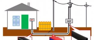
When planning and constructing industrial facilities, power lines are laid based on expediency in various structures, including under a concrete floor screed. Recently, the method of laying electrical wiring in the floor of residential premises is also gaining popularity due to the cost-effectiveness and reliability of electrical installation.
Sometimes laying wiring in the floors may be the only acceptable solution in a panel house, where wall gating is excluded. Also, such electrical installation is resorted to in case of partial renovation of a room, including only updating the bottom covering, or in case of making a belated decision to lay an additional electrical wiring line during the renovation process after finishing the walls.
Like any electrical wiring, underfloor wiring must be installed in accordance with regulatory rules and PUE requirements.
Layout illustrating underfloor wiring
Reduce Electrical Interference
To reduce electrical interference in the cable of an apartment (house), you need to:
- The antenna effect can be reduced by reducing the cable installation height
- Use shielded cables
- Use termination cables with ferrite rings
- Place sensitive devices closer to the floor
In the end, it is worth recalling once again that if you do not have specific knowledge in the field of wiring, in no case should you undertake such work. It is better to entrust this procedure to professionals who have extensive experience. They should be entrusted with all the work, from the selection of wires to further installation of the system. Also, highly qualified specialists will be able to service low-current networks. After all, they have been working professionally in this field for several years and know the main nuances and subtleties of carrying out this work. This is the only way to achieve complete safety and reliability.
4.2.91
The width of the service corridor for switchgear with withdrawable elements and package transformer substations should ensure ease of control, movement and reversal of equipment and its repair.
When installing switchgear and package transformer substations in separate rooms, the width of the service corridor should be determined based on the following requirements:
for single-row installation - the length of the largest of the switchgear trolleys (with all protruding parts) plus at least 0.6 m;
for a double-row installation - the length of the largest of the switchgear trolleys (with all protruding parts) plus at least 0.8 m.
If there is a corridor at the rear of the switchgear and package transformer substations for their inspection, its width must be at least 0.8 m; Individual local narrowings of no more than 0.2 m are allowed.
When installing switchgear and package transformer substations openly in production premises, the width of the free passage must be determined by the location of the production equipment, ensure the possibility of transporting the largest switchgear elements to the switchgear substations, and in any case it must be at least 1 m.
The height of the room must be no less than the height of the switchgear, package transformer substations, counting from busbar entries, jumpers or protruding parts of cabinets, plus 0.8 m to the ceiling or 0.3 m to the beams.
A lower room height is allowed if this ensures the convenience and safety of replacement, repair and adjustment of switchgear equipment, package transformer substations, busbar inputs and jumpers.
Definition of low-current networks and basic requirements for them
The engineering network of a modern building, regardless of its type and affiliation, includes an electrical network, a water and sewerage system, a heating system, as well as low-current systems.
If everything is clear with the three indicated components, every person encounters them in everyday life, then low-current systems cause some confusion for some. Although these devices are used no less often than, for example, a lighting lamp. Low-current systems are Low-current systems that consist of devices that do not consume large currents during operation and are connected to an electrical network of 12 -24 V. The current strength provided by the normal mode of their operation is measured in miles amperes. In technical terminology, these devices and the cable lines connected to them are also called information systems.
The main requirements for the operation of low-current networks include:
- reliability in operation;
- low rate of errors generated;
- low percentage of failures during operation;
- simple management and diagnostics.
Based on such high demands, maintenance of low-current systems should be carried out only by highly qualified specialists in this area.
Only they, with their knowledge and the availability of special diagnostic equipment, can support such information networks at the proper high operating level.
4.2.96
Doors from the switchgear must open towards other rooms or outwards and have self-locking locks that can be opened without a key from the switchgear side.
Doors between compartments of one switchgear or between adjacent rooms of two switchgears must have a device that locks the doors in the closed position and does not prevent the doors from opening in both directions.
Doors between rooms (compartments) of switchgears of different voltages must open towards the switchgear with the lowest voltage.
Locks in the doors of switchgear rooms of the same voltage must be opened with the same key; keys to the entrance doors of the switchgear and other premises should not fit the locks of the cells, as well as the locks of doors in the fences of electrical equipment.
The requirement to use self-locking locks does not apply to switchgear of urban and rural distribution electrical networks with a voltage of 10 kV and below.
Problems and diagrams for installing wiring under the floor
Problems with installing wiring under the floor
Laying electrical wiring under the floor also has its disadvantages. And in order to minimize them as much as possible, it is very important to properly plan the wiring and accurately determine the number of electrical points. After all, making changes in the future will be almost impossible.
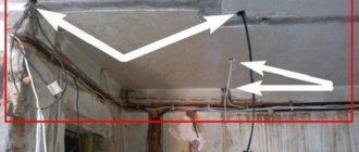
- The main problem that you may encounter with this type of wiring is the difficulty of implementing clause 2.1.23 of the Electrical Installation Code. It requires that all connections and branches of wires be accessible for maintenance and repair.
- This greatly complicates the installation of wiring under the screed layer. After all, in any group network we cannot do without distribution boxes. But we cannot arrange them under the floor.
- There are several ways out of this situation. The simplest seems to be the arrangement of distribution boxes in the wall directly above the floor. But this method is not aesthetically very attractive; there is a possibility that children or pets could get into the box, and if the room is flooded, it generally becomes very dangerous. Therefore, this method is used extremely rarely.
- Much more often, home electrical wiring is installed using socket boxes as junction boxes. Indeed, by connecting each electrical point in series, it is possible to do without distribution boxes. But here lies one huge problem. If the wire feeding a certain electrical point breaks, all subsequent points also become inoperable.
- And of course, it is possible to install a distribution box in a standard location under the ceiling. But this eliminates all the advantages of laying wiring under the floor and leads us to the so-called classic version of hidden wiring.
- From practice I can say that some people ignore clause 2.1.23 of the PUE and install distribution boxes under a layer of screed. But this leads to problems in the future, and these problems can be associated not only with the wiring, but also with the screed due to the insufficient rigidity of the stationary boxes. Therefore, I cannot recommend this installation method to you.
Do-it-yourself electrical wiring under the floor
When you plan to install electrical wiring in a house from scratch, it often becomes a question of choosing the installation method. Everyone wants to do all this with a minimum of effort and as efficiently as possible.
In other articles on our site, we have already considered the options for hidden and open wiring for different options for building materials. In this article we will take a more detailed look at the rules for installing hidden wiring under a layer of screed.
This option has recently become increasingly popular, because when replacing the screed, the rough work of chiselling the walls is significantly reduced.