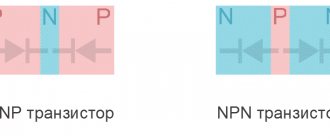
Equivalents of transistor, dinistor, thyristor, varicap, replacement of parts
Modern radio-electronic devices use a very wide range of various electronic devices. Sometimes the absence of one or more of these elements can slow down or even interrupt the installation or layout of a circuit.
Very often there are situations when it is necessary to replace one element with another . If we are talking about simply replacing one value of a resistor or capacitor with another, then the solution to the problem of replacement or selection of a replacement value is obvious. Less obvious are the replacements of radioelements that have specific properties inherent only to them.
Below we will consider the issues of replacing some special semiconductor devices with their equivalents made from more affordable elements.
In pulse technology, controlled and uncontrolled switching elements with a current-voltage characteristic with an N- or S-shaped section are widely used. These are avalanche transistors, gas dischargers, dinistors, thyristors, triacs, unijunction transistors, lambda diodes, tunnel diodes, injection field-effect transistors and other elements.
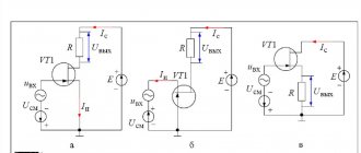
Bipolar avalanche transistors are widely used in relaxation pulse generators and various converters of electrical and non-electric quantities into frequency. It should be noted that such transistors are almost never produced specifically. In practice, ordinary transistors are used for these purposes in an unusual switching on or operating mode.
Analogs of thyristor KU 202
Foreign analogues of the KU202N thyristor are VTX32S100, H20T15CN, 1N4202. Foreign manufacturers do not produce devices with the same geometric dimensions as the KU202N, so you will need to change the location for mounting the device. It should also be taken into account that their parameters may differ slightly from the thyristor in question, for example, the average current may be 7.5 A.
In addition to foreign devices, you can use the Russian analogue - T112-10. Like KU202N, it has a metal body and an anode outlet for thread. However, its dimensions are smaller, so the installation location will still have to be changed.
Equivalent to an avalanche transistor and dinistor
An avalanche transistor is a semiconductor device operating in avalanche breakdown mode. Such a breakdown usually occurs at a voltage exceeding the maximum permissible value.
Thermal breakdown (irreversible damage) of the transistor can be prevented by limiting the current through the transistor (by connecting a high-resistance load).
Avalanche breakdown of a transistor can occur in “direct” and “inverse” switching of the transistor. The avalanche breakdown voltage during inverse connection (the polarity of connecting the semiconductor device is opposite to the generally accepted, recommended one) is usually lower than for “direct” connection.
The base pin of the transistor is often not used (not connected to other circuit elements). In some cases, the base pin is connected to the emitter through a high-resistance resistor (hundreds of kOhms - units of MOhm). This allows you to regulate the avalanche breakdown voltage within certain limits.
In Fig. Figure 1 shows a diagram of an equivalent replacement of the “avalanche” transistor of the K101KT1 integrated chopper with its discrete analogues. It is interesting to note that upon closer examination, this circuit is identical to the equivalent circuit of a dinistor (Fig. 1), a thyristor (Fig. 2) and a unijunction transistor (Fig. 4).
Let us note in passing that the type of current-voltage characteristics of all these semiconductor devices has common characteristic features. Their current-voltage characteristics have an S-shaped section, a section with the so-called “negative” dynamic resistance. Thanks to this feature of the current-voltage characteristic, the listed devices can be used to generate electrical oscillations.
Rice. 1. Analogue of an avalanche transistor and dinistor.
Using a Multimeter to Measure Voltage (Volts)
Set the meter to the highest range provided for AC Volts. It is not yet known what voltage will be the highest, so to avoid damaging the device, we set the indicator to maximum.
- Insert the black probe into the COM or - hole. Volt Figure 1
- Insert the red probe into the V or + hole. Volt Figure 2
- Turn the meter knob to the desired mode (DCV or ACV) (Figure 3). The maximum scale value must coincide with the knob range selector. Voltage readings are linear. Division accuracy up to 0.001 (Figure 4)
- Check the general electrical outlet.
- Insert the black wire into one of the holes in the installed socket, and the red wire into the other. Unplug the wires from the socket and turn the switch knob to the lowest range. Volt Figure 5
- If the pointer did not move, it is likely that DC mode was selected instead of AC. The fact is that this error can be fatal, especially if the measurement is carried out to change the wiring in the apartment, so it is better to check the voltage in both modes.
Figure 3. Selecting the voltage measurement mode in the multimeter Figure 4. Setting the ACV range in the multimeter Figure 5. Measuring the voltage in the socket with a multimeter
Thyristor equivalent
Thyristors, dinistors and similar elements are capable of controlling large powers supplied to the load with very minor internal losses.
Thyristors are devices that have two stable states: a low conductivity state (no conductivity, the device is locked) and a high conductivity state (conductivity is close to zero, the device is open). Representatives of the thyristor class [A.I. Vishnevsky]:
- diode thyristors ( dinistors , diacs), having two terminals (anode and cathode), controlled by applying voltage to the electrodes with a high rate of increase or increasing the applied voltage to a value close to critical;
- triode thyristors ( thyristors , triacs), three-electrode elements, the control electrode of which serves to transfer the thyristor from a closed state to an open state;
- tetrode thyristors having two control electrodes;
- symmetrical thyristors - triacs having a five-layer structure. Sometimes this semiconductor device is called a semistor.
Diode thyristors (dinistors) , the range of which is not so large, differ mainly in the maximum permissible direct forward voltage in the closed state.
Thus, for dinistors of types KN102A, B, V, G, D, E, ZH, I (2N102A - I), the values of these voltages are, respectively, 5, 7, 10, 14, 20, 30, 40, 50 V with reverse current no more than 0.5 mA. The maximum permissible DC on-state current for these semiconductor devices is 0.2 A with a residual on-state voltage of 1.5 V.
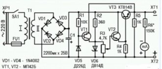
In Fig. Figure 1 shows the equivalent circuit of a low-voltage dinistor. If we take R1 = R3 = 100 Ohm, we can obtain a dinistor with a controlled (using resistor R2) switching voltage from 1 to 25 V [Ya. Voitsekhovsky, R 11/73-40, R 12/76-29]. In the absence of this resistor and under the condition R1 = R3 = 5.1 kOhm, the switching voltage will be 9 B, and with R1 = R3 = 3 kOhm - 12 V.
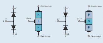
An analogue of a thyristor with a p-p-p-p structure, described in the book by J. Wojciechowski, is shown in Fig. 2. The letter A indicates the anode; K - cathode; UE - control electrode. In the circuits (Fig. 1, 2) transistors of the KT315 and KT361 types can be used.
It is only necessary that the voltage supplied to the semiconductor device or its analogue does not exceed the maximum rated values. The table (Fig. 2) shows what values of R1 and R2 should be used as a guide when creating an analogue of a thyristor based on germanium or silicon transistors.
Rice. 2. Analogue of a thyristor.
In the breaks in the electrical circuit, shown in the diagram (Fig. 2) with crosses, you can include diodes that allow you to influence the type of current-voltage characteristic of the analogue. Unlike a conventional thyristor, its analogue (Fig. 2) can be controlled using an additional output - the control electrode EDOP, connected to the base of the transistor VT2 (top picture) or VT1 (bottom picture).
Typically, the thyristor is turned on by briefly applying voltage to the control electrode of the UE. When voltage is applied to the electrode, the thyristor, on the contrary, can be switched from the on state to the off state.
Using a Multimeter to Measure Voltage (Volts)
Set the meter to the highest range provided for AC Volts. It is not yet known what voltage will be the highest, so to avoid damaging the device, we set the indicator to maximum.
- Insert the black probe into the COM or - hole. Volt Figure 1
- Insert the red probe into the V or + hole. Volt Figure 2
- Turn the meter knob to the desired mode (DCV or ACV) (Figure 3). The maximum scale value must coincide with the knob range selector. Voltage readings are linear. Division accuracy up to 0.001 (Figure 4)
- Check the general electrical outlet.
- Insert the black wire into one of the holes in the installed socket, and the red wire into the other. Unplug the wires from the socket and turn the switch knob to the lowest range. Volt Figure 5
- If the pointer did not move, it is likely that DC mode was selected instead of AC. The fact is that this error can be fatal, especially if the measurement is carried out to change the wiring in the apartment, so it is better to check the voltage in both modes.
Figure 3. Selecting the voltage measurement mode in the multimeter Figure 4. Setting the ACV range in the multimeter Figure 5. Measuring the voltage in the socket with a multimeter
Injection field effect transistor equivalent
An injection field-effect transistor is a semiconductor device with an S-shaped current-voltage characteristic. Such devices are widely used in pulse technology - in relaxation pulse generators, voltage-frequency converters, waiting and controlled generators, etc.
Such a transistor can be made by combining field-effect and conventional bipolar transistors (Fig. 5, 6). Not only the semiconductor structure can be modeled based on discrete elements.
Rice. 5. Analog of an injection field-effect transistor with a n-structure.
Rice. 6. Analog of an injection field-effect transistor with a p-structure.
Equivalent to low voltage gas arrester
In Fig. Figure 7 shows a diagram of a device equivalent to a low-voltage gas discharger [PTE 4/83-127]. This device is a gas-filled cylinder with two electrodes, in which an electrical interelectrode breakdown occurs when a certain critical voltage value is exceeded.
The “breakdown” voltage for an analogue of a gas spark gap (Fig. 7) is 20 V. In the same way, an analogue of, for example, a neon lamp can be created.
Rice. 7. Analogue of a gas discharger - equivalent replacement circuit.
Using a Multimeter to Measure Resistance
Many people do not know how to use a multimeter to measure resistance, but this is its main function, which will be especially useful if you need to install electrical wiring in an apartment or house. Set the multimeter to the Ohm reading by turning the knob to the appropriate reading (Figure 1).
Figure 1. Measuring resistance with a multimeter
Pay attention to the meter readings. If the test leads are not in contact with any object, the pointer needle or analog meter of the tester will deviate to the left; when working with a digital device, the value will “jump” to the larger side. This represents an infinite amount of resistance, or “opening,” but also means that there is no connection path between the black and red probes.
- Connect the black probe to the -COM connector (Figure 2)
- Connect the red probe to the socket marked Omega (the symbol indicating Ohm) or the letter “R” or “P” next to it (Figure 3)
- Set the range (if available) to R x 100 (Figure 4)
- Keep the test lead probes together. The instrument needle should move completely to the right side of the dial. Find "zero settings" and rotate the knob until the meter reads 0 (or as close to 0 as possible) (Figure 5)
Figure 2. Connecting the black probe to -COM Figure 3. Connecting the red probe to the letter P (+) of the multimeter Figure 4. Setting the range on the multimeter Figure 5. Setting the zero on the multimeter
Please note that this position is called “Short Circuit” or “Ohm” at zero” the reading for this range is 1 R X. Ohm Figure 6
Figure 6. Ohms at multimeter zero
Replace batteries (if necessary). If the ohmmeter does not show 0, this may mean that the batteries are low and need to be replaced.
Equivalent replacement of lambda diodes
Semiconductor devices such as lambda diodes and tunnel diodes . The current-voltage characteristics of these devices have an N-shaped section.
Lambda diodes and tunnel diodes can be used to generate and amplify electrical signals. In Fig. 8 and fig. Figure 9 shows circuits simulating lambda di-od [RTE 9/87-35].
In practice, generators often use the circuit shown in Fig. 9 [PTE 5/77-96]. If a controlled resistor (potentiometer) or transistor (field-effect or bipolar) is connected between the drains of the field-effect transistors, then the type of current-voltage characteristic of such a “lambda diode” can be controlled within wide limits: adjust the generation frequency, modulate high-frequency oscillations, etc.
Rice. 8. Analog of a lambda diode.
Rice. 9. Analog of a lambda diode.
Ammeter mode of a multimeter
How to properly use a dt 832, dt 838, dt 830b, dt9205a multimeter in voltage measurement mode in a car? This is not difficult to learn. Set the meter to the highest AC or DC current reading if the Amp range is supported.
Please note that most multimeters will only measure a very small amount of current in the µA and mA ranges. These are values of current that flow only in the finest electronic circuits, and are thousands (and even millions) of times less than the values in any home electrical network. For example, a typical 100W/120V emergency light bulb requires 0.833 amps.
- Insert the black probe into the COM or -.
- Insert the red probe into -. Turn off the power to the circuit, disconnect the isolation transformer.
- An ammeter is placed in series with the circuit to measure current. Polarity must be observed. Current flows from the positive side to the negative side. Set the current range to the highest value (Figure 1)
- Apply power and adjust the data range to decrease. Do not exceed the range of the flow meter, otherwise it may be damaged. A reading of about 2 mA should be indicated since from Ohm's law I = V / R = (9 volts) / (4700 Ω) = 0.00191 = 1.91 mA amps.
Figure 1. Setting the current range
Some important nuances:
- If the multimeter stops working, check the fuse. In some cases it is necessary to use surface terminals (Figure 2)
- Never connect the instrument through a battery voltage source or if it is installed to measure current (amps).
- It is important not only to know how to use the device, but also to choose high-quality devices. Test the device immediately upon purchase!
- In addition to theoretical knowledge, we offer to gain practical skills and watch a video on how to use a dial and analog digital multimeter of the digital series - dt 830v, dt 181, dt9208a, dt 182.
Figure 2. Surface terminals in the
DT 182 multimeter DC CURRENT RANGE CONTENTS 200 mA SAFETY RULES CHARACTERISTICS PANEL DESCRIPTION DC VOLTAGE MEASUREMENT AC VOLTAGE MEASUREMENT DC CURRENT MEASUREMENT RESISTANCE MEASUREMENT DIODE TEST AND CONNECTION TERMINATION BATTERY REPLACEMENT FUSE REPLACEMENT This compact digital multimeter is designed to measure DC, AC current and voltage, resistance, diode testing, audio testing with high accuracy and simplicity.
Lightweight and small in size with a case and probes hidden in the body, this tool will serve you for many years. SAFETY INSTRUCTIONS - Always ensure that the function switch is set to the correct position. — To avoid electrical shock, use CAUTION when measuring high voltages. Always turn off the circuit under test before connecting probes to it. — Before measuring resistance, make sure that all power sources (DC and AC) are turned off. — Never operate the device with the back cover open. Never supply the maximum permissible values of the measured quantities to the input of the device. GENERAL CHARACTERISTICS Measurement method Double integration mode Display 3.5-digit LCD display Polarity Automatic indication Measurement speed 2 - 3 times per second Low battery indicator sign on the left of the display Operating temperature range 0C - 40C, humid. 80%. Dimensions 70 x 120 x 18 mm Weight 110 g. (including battery) 9-12V battery, can be used: GP23A or equivalent Accessories GP23A battery, case, instructions DC VOLTAGE RANGE 2V 20V 200V 500V RESOLUTION 1mV 10mV 0.1V 1V ACCURACY (1 year) 18-2 8C + 0.5% + 1D *) + 0.8% + 1D *) D - least significant unit Maximum permissible input voltage 500 V. AC VOLTAGE RANGE 200 V 500 V RESOLUTION POWER RESOLUTION POWER 0.1 V 1V ACCURACY (1 year) 18-28C + 1.2% + 10D + 1.2% + 10D Operating frequency range: 45 - 1000 Hz. Maximum permissible input voltage 500 Vrms. Indication: indication of the rms value of sinusoidal alternating voltage. 0.1 MAM accuracy (1 year) 18-28s + 2% + 2D protection against overload: fuse of 200 mA/250 V. Resistance range 2 to 20 to 200 to 2000 to accuracy (1 year) 18-28s 1 10 100 1k +1.0 % + 2D Open circuit voltage: approximately 0.65 V. Overload protection: 250 V rms. AC current DIODE TEST RESOLUTION 1 mV TEST CURRENT 0.8 mA MAX. OPEN VOLTAGE CIRCUIT 3.2 V Overload protection: 250 V rms. AC current CONNECTION CONNECTION RESOLUTION 1 DESCRIPTION Sound signal when resistance. less than 50 Overload protection: 250 V rms. AC current INSTRUCTIONS FOR USE DC VOLTAGE MEASUREMENT 1. Set the function switch to the V= position 2. Set the limit switch to the desired position. If the voltage being measured is not known in advance, set the range switch to the highest limit, and then reduce the limit until the required accuracy is achieved. 3. Connect the test leads to the voltage source or load being measured. The indicator will show the voltage and its polarity on the red probe of the device. 4. When the limit switch is set to the “500 V” position, the “HV” sign will appear on the display, reminding you of working with high voltage. Caution required. AC VOLTAGE MEASUREMENT 1. Set the function switch to position V 2. Set the limit switch to the desired position. Measurements can be carried out with the switch position 2V and 20V, but accuracy is not guaranteed. 3. Connect the test leads to the voltage source or load being measured. Read the readings on the display. 4. When the limit switch is set to the “500 V” position, the “HV” sign will appear on the display, reminding you of working with high voltage. Caution required. DC CURRENT MEASUREMENT 1. Set the function switch to position A. 2. Set the limit switch to the 200 mA position. Readings are possible with other limit switch positions, but the decimal point will not be displayed correctly. 3. Open the circuit being measured and connect the probes of the device in series with the load in which the current is measured. 4. Read the current value and its polarity on the display. RESISTANCE MEASUREMENT 1. Set the function switch to position. 2. Set the limit switch to the desired position. 3. If the resistor being measured is in the circuit, turn off the power and discharge all capacitors before connecting the test leads. 4. Connect the probes to the resistor being measured and read the resistance value on the display. DIODE TEST AND CONNECTION TERMINATION 1. Set the function switch to position. 2. Set the limit switch to position. Connect the red probe to the anode, and the black probe to the cathode of the diode under test. Read the forward voltage drop across the diode in millivolts on the display. When the diode is turned on in reverse, only “1” will appear on the display. 4. Connect the probes to two points of the circuit, the signal will sound when the circuit resistance is less than 50 Ohms. CHANGING THE BATTERY 1. When the battery is low, a sign appears on the left of the display. 2. Before replacing the battery, turn off the multimeter and disconnect the probes from the circuits being measured. 3. Remove the screw on the back cover and open it. Replace the battery, observing the correct polarity. WARNING Do not operate the instrument until the back cover is closed. REPLACING THE FUSE The fuse rarely needs replacing and almost always blows as a result of operator error. To replace the fuse, unscrew the screw on the back cover and open it, as when replacing the battery. Replace the fuse with the same type. WARNING 1. Before replacing a fuse, make sure the range switch is in the “OFF” position and disconnect the test leads from the circuits being measured. 2. To prevent fire, use fuses with current/voltage values similar to the current/voltage values of the factory installed fuse (200mA/250V). sockets in Pushkino
Equivalent replacement for tunnel diodes
Rice. 10. Analogue of a tunnel diode.
Tunnel diodes are also used to generate and amplify high-frequency signals. Some representatives of this class of semiconductor devices are capable of operating at frequencies that are hardly achievable under normal conditions - on the order of several GHz. A device that allows you to simulate the current-voltage characteristic of a tunnel diode is shown in Fig. 10 [R 4/77-30].
Varicap equivalent circuit
Varicaps are semiconductor devices with variable capacitance. The principle of their operation is based on the change in the barrier capacitance of the semiconductor junction when the applied voltage changes.
More often, reverse bias is applied to the varicap, less often - forward bias. Such elements are usually used in tuning units for radio and television receivers. Conventional diodes and zener diodes (Fig. 11), as well as their semiconductor analogues (Fig. 12, Fig. 13 [PTE 2/81-151]) can be used as varicaps.
Rice. 12. Diagram of a varicap analogue.
Rice. 13. Circuit diagram of a varicap analogue based on a field-effect transistor.
Literature: Shustov M.A. Practical circuit design (Book 1).
- PCBWay - only $5 for 10 PCBs, first order for new customers is FREE
- PCB Assembly from $88 + FREE Shipping Worldwide + Stencil
- Online Gerber file viewer from PCBWay!
ATTENTION! In the original book, an error was found in Figures 1 and 2: an NPN transistor was connected to the Anode, instead of a PNP. In the current article, in the pictures, the errors have been corrected! Found errors and notified us about them - Ivan Ivanovich.
It is better to replace the dinistor with a thyristor and a zener diode or a chain of zener diodes from the anode to the control, it has been tested - it works reliably, looking for PNP transistors at 250-300v is problematic.
NIKOLAY, you can unearth a couple of burnt-out foreign TV sets, delve into the line scan, take the output transistors from there (as far as I remember, they are direct conduction). If not, you can make an analogue of an npn transistor from several pnp transistors. I will reveal the principle of operation of the replacement circuit. When applying to the base of the direct conduction transistor pnp structure of a negative pulse, it opens. The reverse conduction transistor npn structure closes. So, by closing one transistor, you can open another, simulating the operation of a direct conduction transistor. In this case, however, the collector capacitance increases, but it can be compensated by introducing reverse communication. In this case, however, the gain decreases, but this can be corrected by increasing the number of stages.
You can also take a closer look at the key in the power supply.
Using a Multimeter to Measure Resistance
Many people do not know how to use a multimeter to measure resistance, but this is its main function, which will be especially useful if you need to install electrical wiring in an apartment or house. Set the multimeter to the Ohm reading by turning the knob to the appropriate reading (Figure 1).
Figure 1. Measuring resistance with a multimeter
Pay attention to the meter readings. If the test leads are not in contact with any object, the pointer needle or analog meter of the tester will deviate to the left; when working with a digital device, the value will “jump” to the larger side. This represents an infinite amount of resistance, or “opening,” but also means that there is no connection path between the black and red probes.
- Connect the black probe to the -COM connector (Figure 2)
- Connect the red probe to the socket marked Omega (the symbol indicating Ohm) or the letter “R” or “P” next to it (Figure 3)
- Set the range (if available) to R x 100 (Figure 4)
- Keep the test lead probes together. The instrument needle should move completely to the right side of the dial. Find "zero settings" and rotate the knob until the meter reads 0 (or as close to 0 as possible) (Figure 5)
Figure 2. Connecting the black probe to -COM Figure 3. Connecting the red probe to the letter P (+) of the multimeter Figure 4. Setting the range on the multimeter Figure 5. Setting the zero on the multimeter
Please note that this position is called “Short Circuit” or “Ohm” at zero” the reading for this range is 1 R X. Ohm Figure 6
Figure 6. Ohms at multimeter zero
Replace batteries (if necessary). If the ohmmeter does not show 0, this may mean that the batteries are low and need to be replaced.
Schematic diagram
Conclusion (A)
corresponds to the anode,
(K)
to the cathode,
(C)
to the control electrode. The current-voltage characteristic of the circuit corresponds to the one given above, so that it (the circuit) can be considered an analogue of a triode thyristor (thyristor). If the control electrode is not connected, you will get an analogue of a diode thyristor (dinistor).
The circuit uses complementary pairs of transistors. They have the same base-emitter and collector-emitter saturation voltages. We most often use KT502, KT503. Resistors R2 and R3 are equal to each other.
Examination of the board and circuit
Interestingly, in the lowest measurement range the DM100 has 3 decimal places. And of course, to complete the review, it’s worth looking under the lid.
What surprised me was the number of elements soldered on the board; there are more than a hundred resistors! There are also integrated circuits, a dozen transistors, on-board sensors and other passive elements.
When looking at the circuit, this “wheel of 310 resistors” was confusing. This looks like an encoder position knob and it turns out to have nothing to do with the measurement. The pins in the microcontroller are simply read using an ADC.
All this proves that the DM100 is not a completely inexpensive version of a multimeter, and the manufacturer allowed designers to be inventive.
For our needs, the multimeter should best measure I, U and R. The remaining additional functions are not particularly needed. To measure frequency, capacitance or inductance, devices specifically designed for this purpose are usually used.
In this review we will not describe all these additional features, such as NCV or extended measurement ranges; everyone can find this in the instructions. We also do not intend to praise or criticize certain aspects. Everyone can estimate the value of what they want to buy.
We can only add that the MESTEK DM100 meter met expectations in terms of measurement speed, accuracy and determination of leakage currents of electrolytic capacitors.
The multimeter has a manual change of measurement ranges. It's unclear why these things are still being produced. Maybe this makes sense for educational purposes. However, when it comes to practical use, this is an inconvenient solution. For example, the AN870 with auto-selection is noticeably better in terms of ergonomics, although much cheaper! The photos below are for MESTEK DM100 and ANENG AN870:
True, sometimes manual changes are useful. We have UNI-T with automatic range, and sometimes it's annoying if the value is on the border, it flashes the dot, that is, it changes the range back and forth, and the value is not really displayed.