One of the main components of a truly high-quality seam is the correct and precise adjustment of the welding current in accordance with the task at hand. Experienced welders often have to work with metal of different thicknesses, and sometimes the standard min/max adjustment is not enough for proper work. In such cases, there is a need for multi-stage current regulation, accurate to the nearest ampere. This problem can be easily solved by connecting an additional device to the circuit - a current regulator.
The current can be adjusted in the secondary (secondary winding) and in the primary (primary winding). Moreover, each method of setting up a transformer for welding has its own characteristics that are important to consider. In this article we will tell you how to regulate the current in welding machines, provide diagrams of regulators for a semi-automatic welding machine, and help you choose the right welding current regulator for the primary winding for a welding transformer.
Methods for adjusting current
There are many ways to regulate the current, and above we wrote about the secondary and primary windings. In fact, this is a very rough classification, since the adjustment is still divided into several components. We will not be able to analyze all the components within the framework of this article, so we will focus on the most popular ones.
One of the most commonly used current control methods is to add a ballast at the output of the secondary winding. This is a reliable and durable method; you can easily make a ballast with your own hands and use it without additional equipment. Often, ballasts are used solely to reduce current.
In this article, we described in detail the operating principle and features of using a ballast for a semi-automatic welding machine. There you will find detailed instructions on how to make the device at home and how to use it in your work.
Despite many advantages, the method of adjusting the current through the secondary winding when used in conjunction with a welding transformer may not be very convenient, especially for novice welders. First of all, the ballast is quite bulky and its size can reach a meter in length. The device is also often underfoot and gets very hot, and this is a gross violation of safety regulations.
If you are not ready to put up with these shortcomings, then we recommend that you pay attention to the method when the welding current is adjusted through the primary winding. For these purposes, electronic devices that can be easily made with your own hands are often used. Such a device will easily regulate the current through the primary and will not cause inconvenience to the welder during operation.
The electronic regulator will become an indispensable assistant for a summer resident who is forced to weld under conditions of unstable voltage. Often houses are simply not allowed to use electrical appliances larger than 3-5 kW, and this is very limiting in their work. Using the regulator, you can configure your device so that it can operate smoothly even with low voltage. Also, such a device will be useful for craftsmen who need to constantly move from place to place while working. After all, the regulator does not need to be dragged around like a ballast, and it will never cause injury.
Now we will talk about how to make an electronic regulator from thyristors yourself.
General concepts
The principle of arc welding is well known. Let's refresh our memory of the basic concepts. To obtain a welding joint, an arc must be created. An electric arc occurs when voltage is applied between the welding electrode and the surface of the material being welded. The arc current melts the metal, forming a molten pool between the two ends. After the seam has cooled, we obtain a strong connection between the two metals.
Arc welding diagram.
In Russia, alternating current is regulated at a frequency of 50 Hz. Power for the welding machine is supplied from the mains with a phase voltage of 220 V. Welding transformers have two windings: primary and secondary. The secondary voltage of the transformer is 70 V.
Separate manual and automatic welding modes. In a home workshop, welding is carried out manually. We list the parameters that can be changed manually:
- welding current;
- arc voltage;
- welding electrode speed;
- number of passes per seam;
- diameter and brand of electrode.
The correct selection and maintenance of the necessary parameters throughout the welding process are the key to a high-quality welded joint..
When carrying out manual arc welding, it is necessary to correctly distribute the current. This will allow you to make a high-quality seam. The stability of the arc directly depends on the magnitude of the welding current. Experts select it based on the diameter of the electrodes and the thickness of the materials being welded.
Thyristor regulator circuit
Above you can see a diagram of a simple regulator using 2 thyristors with a minimum of non-scarce parts. You can also make a regulator using a triac, but our practice has shown that a thyristor power regulator is more durable and operates more stably. The assembly diagram is very simple and according to it you can quickly assemble the regulator with minimal soldering skills.
The operating principle of this regulator is also simple. We have a primary winding circuit into which the regulator is connected. The regulator consists of transistors VS1 and VS2 (for each half-wave). The RC circuit determines the moment when the thyristors open, and at the same time the resistance R7 changes. As a result, we get the opportunity to change the current in the primary of the transformer, after which the current changes in the secondary.
Note! The regulator is adjusted under voltage, do not forget about this. To avoid fatal mistakes and avoid injury, it is necessary to isolate all radio elements.
In principle, you can use old-style transistors. This is a great way to save money, since these transistors can easily be found in an old radio or at a flea market. But keep in mind that such transistors must be used at an operating voltage of at least 400 V. If you find it necessary, you can use dinistors instead of the transistors and resistors shown in the diagram. We did not use dinistors, since in this version they do not work very stably. In general, this thyristor-based welding current regulator circuit has proven itself well, and on its basis many regulators have been manufactured that operate stably and perform their function well.
You could also see in stores the resistance welding regulator RKS-801 and the resistance welding regulator RKS-15-1. We do not recommend making them yourself, since it will take a lot of time and will not save you much money, but if you want, you can make RKS-801. Below you see a diagram of the regulator and a diagram of its connection to the welder. Open the pictures in a new window to see the text better.
DIY power regulator for welding transformer
» Articles » Do-it-yourself current regulator for a welding machine
Each control method can have a positive effect on the operation of the welding unit, but each method also has its own disadvantages, which it is advisable to know and be able to avoid unpleasant situations. The welding process is a responsible procedure, therefore it determines almost any deviation from the norms.
Using special regulators:
- The operating current is adjusted,
- The magnetic flux changes.
Therefore, the current regulator for a welding machine performs an important function and the main methods of regulation are: magnetic shunting, mobility of windings, as well as various types of chokes.
Methods for adjusting welding parameters
If you connect to the taps that are made on the second winding of the transformer, then there is the possibility of stepwise regulation of the electric current. When using this method, the number of turns changes, thus reducing or increasing the current.
Welding current measurement
Once you have made and configured the regulator, it can be used in operation. To do this, you need another device that will measure the welding current. Unfortunately, it will not be possible to use household ammeters, since they are not capable of working with semi-automatic devices with a power of more than 200 amperes. Therefore, we recommend using a clamp meter. This is a relatively inexpensive and accurate way to find out the current value; the clamp control is clear and simple.
Read also: Main products of ferrous metallurgy
The so-called “clamps” at the top of the device grip the wire and measure the current. There is a current measurement limit switch on the device body. Depending on the model and price, different manufacturers make clamp meters capable of operating in the range of 100 to 500 amps. Choose a device whose characteristics match your welding machine.
Clamp meters are an excellent choice if you need to quickly measure current without interfering with the circuit or connecting additional elements to it. But there is one drawback: clamps are absolutely useless when measuring DC current values. The fact is that direct current does not create an alternating electromagnetic field, so the device simply does not see it. But when working with alternating current, such a device meets all expectations.
There is another way to measure current, it is more radical. You can add an industrial ammeter to the circuit of your semi-automatic welding machine, capable of measuring large current values. You can also simply temporarily add an ammeter to the open circuit of the welding wires. On the left you can see a diagram of such an ammeter, according to which you can assemble it.
This is a cheap and effective way to measure current, but using an ammeter in welding machines also has its own characteristics. It is not the ammeter itself that is added to the circuit, but its resistor or shunt, and the dial indicator must be connected in parallel to the resistor or shunt. If you do not follow this sequence, the device, at best, simply will not work.
Changing the number of turns
With this method, the arc characteristics are adjusted by changing the transformation ratio. The transformation ratio can be changed by additional taps from the secondary coil. By switching from one tap to another, you can change the voltage in the output circuit of the device, which leads to a change in arc power.
The regulator must withstand high welding current. The disadvantage is the difficulty of finding a switch with such characteristics, a small range of adjustments and discreteness of the transformation ratio.
Versatile capabilities and tasks performed
A friend needed a machine for welding and cutting pipes, angles, sheets of different thicknesses with the ability to work with 3÷5 mm electrodes. Welding inverters were not known at that time.
We settled on the DC design, as it is more universal and provides high-quality seams.
Thyristors removed the negative half-wave, creating a pulsating current, but did not smooth out the peaks to an ideal state.
The welding output current control circuit allows you to adjust its value from small values for welding up to 160-200 amperes required when cutting with electrodes. She:
- made on a board from thick getinax;
- covered with a dielectric casing;
- mounted on the housing with the output of the adjusting potentiometer handle.
The weight and dimensions of the welding machine were smaller compared to the factory model. We placed it on a small cart with wheels. To change jobs, one person rolled it freely without much effort.
The power cord was connected through an extension cord to the connector of the input electrical panel, and the welding hoses were simply wound around the body.
Simple design of DC welding machine
Based on the installation principle, the following parts can be distinguished:
- homemade transformer for welding;
- its power supply circuit is from network 220;
- output welding hoses;
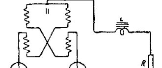
- power unit of a thyristor current regulator with an electronic control circuit from a pulse winding.
Pulse winding III is located in power zone II and is connected through capacitor C. The amplitude and duration of the pulses depend on the ratio of the number of turns in the capacitor.
How to make the most convenient transformer for welding: practical tips
Theoretically, you can use any model of transformer to power the welding machine. The main requirements for it:
- provide arc ignition voltage at idle speed;
- reliably withstand the load current during welding without overheating the insulation from prolonged operation;
- meet electrical safety requirements.
In practice, I have come across different designs of homemade or factory-made transformers. However, they all require electrical engineering calculations.
I have been using a simplified technique for a long time, which allows me to create fairly reliable transformer designs of medium accuracy class. This is quite enough for household purposes and power supplies for amateur radio devices.
It is described on my website in an article about making a transformer soldering iron Moment with your own hands. This is an average technology. It does not require clarification of the grades and characteristics of electrical steel. We usually don’t know them and cannot take them into account.
Features of core manufacturing
Craftsmen make magnetic wires from electrical steel of various profiles: rectangular, toroidal, double rectangular. They even wind coils of wire around the stators of burnt-out powerful asynchronous electric motors.
We had the opportunity to use decommissioned high-voltage equipment with dismantled current and voltage transformers. They took strips of electrical steel from them and made two donut rings out of them. The cross-sectional area of each was calculated to be 47.3 cm 2 .
They were insulated with varnished cloth and secured with cotton tape, forming a figure of a reclining figure eight.
They began to wind the wire on top of the reinforced insulating layer.
Secrets of the power winding device
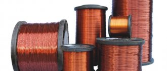
The wire for any circuit must have good, durable insulation, designed to withstand long-term operation when heated. Otherwise, it will simply burn during welding. We proceeded from what was at hand.
We received a wire with varnish insulation, covered with a fabric sheath on top. Its diameter - 1.71 mm is small, but the metal is copper.
Since there was simply no other wire, they began to make the power winding out of it with two parallel lines: W1 and W'1 with the same number of turns - 210.
Read also: Solenoid valve operating principle
The core donuts were mounted tightly: this way they have smaller dimensions and weight. However, the flow area for the winding wire is also limited. Installation is difficult. Therefore, each power half-winding was separated into its own magnetic circuit rings.
In this way we:
- doubled the cross-section of the power winding wire;
- saved space inside the donuts to accommodate the power winding.
Wire alignment
You can get a tight winding only from a well-aligned core. When we removed the wire from the old transformer, it turned out to be bent.
We figured out the required length in our minds. Of course it wasn't enough. Each winding had to be made from two parts and spliced with a screw clamp directly on the donut.
The wire was stretched along its entire length on the street. We picked up the pliers. They clamped the opposite ends and pulled with force in different directions. The vein turned out to be well aligned. They twisted it into a ring with a diameter of about a meter.
Technology of winding wire on a torus
For the power winding, we used the rim or wheel winding method, when a large-diameter ring is made of wire and wound inside the torus by rotating one turn at a time.
The same principle is used when putting a winding ring on, for example, a key or keychain. After the wheel is inserted inside the donut, they begin to gradually unwind it, laying and fixing the wire.
This process was well demonstrated by Alexey Molodetsky in his video “Winding a torus on a rim.”
This work is difficult, painstaking, and requires perseverance and attention. The wire must be laid tightly, counted, the process of filling the internal cavity must be monitored, and the number of turns wound must be recorded.
How to wind a power winding
For it, we found a copper wire of a suitable cross-section - 21 mm 2. We estimated the length. It affects the number of turns, and the no-load voltage necessary for good ignition of the electric arc depends on them.
Typically reference books recommend 60-70 volts. One experienced welder told us that in our case 50 would be enough. We decided to check it, and if it wasn’t enough, then increase the winding further.
We made 48 turns with the middle terminal. In total, there were three ends on the donut:
- middle - for direct connection of the “plus” to the welding electrode;
- the outer ones - to the thyristors and after them to ground.
Since the donuts are fastened together and the power windings are already mounted on them along the edges of the rings, the winding of the power circuit was carried out using the “shuttle” method. The aligned wire was folded like a snake and pushed through the holes of the donuts for each turn.
The middle point was unsoldered using a screw connection and insulated with varnished cloth.
Operation of the ballast connection
The ballast resistance of the control apparatus is at the level of 0.001 Ohm. It is selected through experiment. Directly to obtain resistance, resistance wires of high power are mainly used; they are used in trolleybuses or on lifts.
You can even reduce the high frequency welding voltage by using a steel door spring.
Such resistance is turned on permanently or in another way, so that in the future it will be possible to easily adjust the indicators. One edge of this resistance is connected to the output of the transformer structure, the other is provided with a special clamping tool that can be thrown along the entire length of the spiral, which will allow you to select the desired voltage force. The main part of resistors using high-power wire is produced in the form of an open spiral. It is mounted on a structure half a meter long. Thus, the spiral is also made from heating element wire. When resistors made of a magnetic alloy are combined with a spiral or any part made of steel, in the process of passing high current, it will begin to tremble noticeably. The spiral has such dependence only until the moment it stretches.
Reliable welding current control circuit
The work involves three blocks:
- stabilized voltage;
- formation of high-frequency pulses;
- separation of pulses into circuits of thyristor control electrodes.
Voltage stabilization
An additional transformer with an output voltage of about 30 V is connected from the power winding of the 220 volt transformer. It is rectified by a diode bridge based on D226D and stabilized by two zener diodes D814V.
In principle, any power supply with similar electrical characteristics of current and output voltage can work here.
Pulse block
The stabilized voltage is smoothed by capacitor C1 and supplied to the pulse transformer through two bipolar transistors of direct and reverse polarity KT315 and KT203A.
Transistors generate pulses to the primary winding Tr2. This is a toroidal type pulse transformer. It is made of permalloy, although a ferrite ring can also be used.
Winding of three windings was carried out simultaneously with three pieces of wire with a diameter of 0.2 mm. Made 50 turns. The polarity of their inclusion matters. It is shown by dots in the diagram. The voltage on each output circuit is about 4 volts.
Windings II and III are included in the control circuit for power thyristors VS1, VS2. Their current is limited by resistors R7 and R8, and part of the harmonic is cut off by diodes VD7, VD8. We checked the appearance of the pulses with an oscilloscope.
In this chain, the resistors must be selected for the voltage of the pulse generator so that its current reliably controls the operation of each thyristor.
The unlocking current is 200 mA, and the unlocking voltage is 3.5 volts.
Welding current regulation
Variable resistor R2, with its resistance, determines the position of each pulse passed through the control electrode of the thyristor. The shape of the pulsating current at the output of the power circuit of the welding machine depends on it.
Half-sine ripples can pass through completely when the welding current is set to maximum or be cut off to almost zero.
Personal impressions of use
When the DC welding machine was made with our own hands, we began to study its capabilities. First of all, we experimented with the polarity of the electrode connection and identified a pattern.
The electrode can be supplied with “plus” - direct polarity or “minus” - reverse polarity. In this case, the depth of weld penetration changes. With reverse polarity it increases by about 40-50%.
Our welding machine allows you to weld with 3 mm electrodes, providing a welding current of 80 amperes for quite a long time. The heating of the structure does not exceed operating conditions. At the same time, the load in the household wiring network is maintained at a level of up to 20 A.
If there is a need to use 4 mm electrodes or increase the welding current, then it is necessary to organize breaks in work to cool the machine. Ours is natural: due to cracks and holes.
The cooling system can be enhanced by forced ventilation by blowing. But we did not deal with this issue.
I show the scanned handwritten text of a preserved document. It may be useful for repetition.
And now I recommend watching the video by the owner of zxDTCxz “Welding machine based on a toroidal magnetic core.” It contains many useful recommendations.
If you still have questions on the topic, then ask them in the comments, I will answer.
- 5
- 4
- 3
- 2
- 1
(5 votes, average: 5 out of 5)
Subscribe to our “Home Master” newsletter and you will always be the first to know about the news from this blog!
Hello. What if the transformer is W-shaped? Can you advise? I'm assembling a welding machine.
Hello, Alexander. The operating principle is the same. However, send photos to the site’s email (see section “About the site”) and describe the dimensions of the magnetic core iron. This will help me make a power calculation. Also read the comments to the article about the design of the homemade Moment soldering iron. There I devoted a lot of time to this issue. You will need it.
Read also: Attachments for a hammer drill for removing tiles
Hello Dear Alexey! Thank you for your article, very useful and interesting! Tell me, I have a couple of questions! My initial power source is already ready 36 volts DC, if I exclude the very beginning of the so-called transformer from this circuit, will this circuit work? Or is it not suitable for me? Need something else? I'll be looking forward to your answer! thank you in advance!
Hello, Pavel. I didn't quite understand your question. Let's clarify: you have a ready-made voltage source that gives an output of 36 volts. Did I understand correctly that you want to use it to make a DC welder? For reliable arc ignition you need 60-70 volts. In my case, it turned out to light it from 50. I didn’t experiment below, try it, but it’s unlikely that you’ll get anything good... One more important electrical characteristic is the output power. If this is not provided, the welding machine will simply burn out. I created it at 50Vx160A=8kW. Pay attention to the power circuits of your source, will they withstand such power? Actually, I advise you to do the calculation based on the initial problem: what electrodes are you going to use to cook and cut. It is necessary to create an electric arc current under them and ignite it. This will determine the output power of the welder. The design is calculated and parts are selected based on these parameters. Send us a photo of your unit. Or better yet, a diagram. Then it will be possible to give more specific recommendations.
Victor, the ignition voltage depends on the characteristics of the welding electrode. With the right choice of electrode, welding work goes well at Ux.x. welder 36 volts or less.
Thanks for the addition. Alexander. Pavel has already explained this to me too. I'm just not a welder, but a simple electrician.
I work as a welder in the north, I travel urgently to emergency situations! Situations often began to occur when the welding generator needed to be dragged directly into the swamp or to perform certain welding jobs - this was very difficult and sometimes extremely impracticable! But I go to the site on a tracked all-terrain vehicle with 24 volt batteries installed. It is not difficult to remove them and quickly bring them to the place! 24 volts does not cook well, but when connecting the battery. up to 36 volts cooks perfectly! but last week a situation happened that I tried to weld the break for too long and my battery exploded! Dear Alexey, I ask you to help me in this matter because after reading your article I realized that you are a professional in this matter! Is it possible to adjust your circuit to 36 volts DC, or 24 if necessary, I can connect two to 48 volts
Well, I use 2.0 and 2.5 mm electrodes, sometimes I use 3 mm. current for them from 70 to 110 amperes for the eyes 36 volts cooks well, well, more precisely, it cooked! As you understand, it was shorted to a straight line! I understand that, of course, this is nonsense and everything should be correct and according to science! That's why I turned to you! 110 is even a lot, rarely when I set it to more than 100 it means 70-100 amperes
Pavel, doing welding from a battery assembly is not the best option, but it works quite well for emergency situations. We must take into account the risk of losing the battery. What needs to be taken into account in my opinion: 1. All banks must be well charged. Any defective bank will work to discharge the battery, taking its current onto itself. 2. Welding must be done quickly. Otherwise, the electrolyte will boil and the battery will explode. Before my eyes, while serving in the army, a mechanic driver of a self-propelled tractor dropped a wrench about 22x24 in size onto the battery output tires. The arc was such that the key burned out, but the banks survived. They started a diesel engine with 500 horses. I don’t remember the amps, but the assembly was made from tank batteries. It was difficult to drag them even with two people. I return to our welding. We assume that the maximum current should be 110 amperes. It should be issued by the battery. A voltage of 48 volts should be sufficient. If you worked from 36, then you can also use it, but 48 is better. The mode of short circuiting batteries through the electrode is not very good. It must be limited by electrical resistance. For DC circuits, I recommend using a CMOS series bipolar transistor. The control circuit that I made for a welder using rectified current will not work. Here it is pure constant and everything works differently. I’ll think about the scheme tomorrow and propose something that, in my opinion, is most suitable.
Pavel, I haven’t found a decent circuit that a beginner with minimal electronics skills can assemble. Many mistakes can be made. I propose to connect an inverter to the battery, converting constant voltage into 220 volts, and power the welding inverter from it. All this equipment can be simply purchased. The heating of the electrolyte in batteries must be controlled; it must not be allowed to boil.
Good day Pavel, I have such a device as ISKRA Universal vd 0801 knot. I encountered this factor while working. During operation, it buzzed very loudly and the diodes flew out. I replaced all 16 diodes with new ones. turned it on and inserted the jumper into the block. and everything happened again. what could be the problem. There is very little said on the Internet about such a device, maybe you can help. thank you in advance
Hello, Ivan. I have not encountered such a device, there is no diagram. What I found on the Internet raises doubts and requires verification. However, we have experience with repairing such devices. I think we'll repair it. I need a diagram and detailed photos. Send what you have to the site's email. I will get acquainted with the design and tell you what to do. You will need a multimeter or an old tester for electrical measurements. Battery, flashlight bulb. wires. I'm waiting for additional information.
Power Electronics
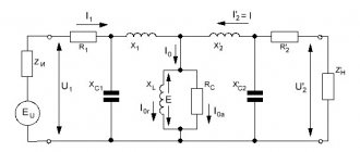
On the Internet they posted a diagram of a current regulator for an inductive load. I wanted to know the opinion of my colleagues on this device.
Last edited by navigator!! 23-02, 20:30, edited 2 times in total.
In the second picture
It looks like the arc stabilizer is screwed on (arc ignition device). Therefore, in principle, it will cook without throttle. This turns out to be a type of thyristor welding transformer. Similar ones are described in Zacks’ book, which is in the Books and Magazines section.
I'll write a little later. I have experience in operating such a device, that is, at the output there is a bridge with two thyristors, but without a choke.
I continue. So, in the magazine “Radio” No. 7.1996, a device diagram was proposed in which both the adjustment of the output current and the formation of the required slope of the characteristic are carried out by controlling the cut-off angle of the sinusoidal voltage. The text of the article can be found, for example, here: https://www.qrz.ru/schemes/contribute/digest/svarka04.shtml The author shows that pauses in arc burning do not have a fatal effect on its stability if the duration of the pauses is less 50 ms (maximum permissible recovery time of the output voltage, after a short circuit, drops of melt, for example). Experience in operating the apparatus, built taking into account the recommendations from the mentioned journal article, revealed: - the manufactured copy of the apparatus cooks well with electrodes for alternating current. UONI, despite the DC output, does not “burn”, IMHO, not because of the pauses themselves, but because of the rather low open-circuit voltage - 42V. - with electrodes that are unpretentious to this parameter (and this, unfortunately, is a change), combustion stability is, in principle, good. At times, however, there is some difficulty in ignition. - at the lowest currents (the voltage xx is set higher, the arc burning time is shorter), the arc is literally rubbery, stretches behind the electrode so that it really interferes with the work. But this drawback can be relatively easily eliminated by modifying the circuit.