A triac is a semiconductor switch for alternating current. The international name TRIAC is often found, which means the same thing (TRIode for Alternate Current). To understand the structure of a triac (symmetrical thyristor) and learn how to test a triac, it is important to first understand that it consists of two back-to-back thyristors (if absolutely correct, thyristors, but thyristors are used more often) having a common control circuit. Now it remains to understand what a thyristor is.
KOMITART - entertainment and educational portal
Sections of the site
- " To home
- » Radio amateur
- » APEX AUDIO
- " Power supplies
- » Guitar accessories
- » Do it yourself
- » For motorists
- » Service-Manual
- » PREAMPLIFIERS
- » Free programs
- " Computer
- » Books
- " Women things
- We cook deliciously and quickly
- » Games on the site
- " Humor
- » Miscellaneous - interesting
DirectAdvert NEWS
GNEZDO NEWS
friends of site
Statistics
Simple built-in power regulators.
Every home has household electrical appliances powered by AC power.
You can increase the functionality and usability of many of these devices by adjusting their power consumption. One of the most common principles of power regulation in AC networks is phase. The phase control method uses the relationship between the moment (phase) of opening of the control element relative to the beginning of the half-cycle of the supply voltage and the power consumed by the device.
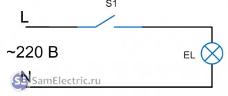
To regulate power, a key element is used, which is most conveniently used as a triac. By changing the delay (phase) of the triac opening time relative to the beginning of the half-wave of the mains supply voltage, you can regulate the power consumed by the load from almost 0 to 100%. The dependence of the load voltage on the opening phase of the triac is shown in Fig. 1
.
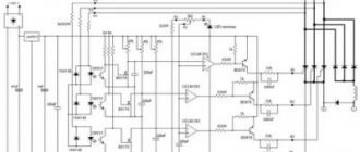
The operation of all the regulators below is based on the phase control principle. They differ in the maximum permissible power of the connected load. The regulator, assembled according to the diagram shown in Fig. 3, can connect an AC load with a power of up to 1000 W. To the regulator assembled according to the diagram in Fig. 6 - up to 2500 W. These regulators will allow you to control the power of electric heating and lighting devices (including the heating temperature of an electric soldering iron), and regulate the rotation speed of asynchronous AC motors (fan, electric sander, electric drill, etc.). Thanks to the wide range of adjustment and high power, the regulators will find the widest application in our everyday life.
POWER REGULATOR FOR 1000 W/220 V.
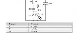
Power regulator for 1000 W/220 V. The general view of this device is shown in Fig. 2, electrical circuit diagram in Fig. 3.
List of circuit elements up to 1000 W.
• C1 - 0.1 µF • R1 - 4.7 kOhm • VR1 - 500 kOhm (Variable resistor) • DIAC - DB3 (dinistor) • TRIAC - BT136600E (triac) • D1 - 1N4148 • LED - yellow LED
DESCRIPTION OF WORK.
The triac power regulator uses the principle of phase control. The principle of operation of the regulator is based on changing the moment the triac is turned on relative to the transition of the mains voltage through zero (the beginning of the positive or negative half-wave of the supply voltage).
At the beginning of the positive half-cycle, the triac is closed. As the mains voltage increases (Fig. 1), capacitor C1 is charged through the divider R1, VR1. The rising voltage on capacitor C1 lags (phase shifts) from the mains voltage by an amount depending on the total resistance of resistors R1, VR1 and capacitance C1. The capacitor continues to charge until the voltage across it reaches the “breakdown” threshold of the dinistor (about 32 V). As soon as the dinistor opens (hence, the triac also opens), a current determined by the total resistance of the open triac and the load will flow through the load. The triac remains open until the end of the half-cycle. Resistor VR1 sets the opening voltage of the dinistor and triac. Those. This resistor regulates the power. During the action of the negative half-wave, the principle of operation of the circuit is similar. The LED indicates the operating mode of the power regulator.
Structurally, the circuit is made on a printed circuit board made of foil fiberglass with dimensions of 38x27 mm.
Main parameters of triacs BT136-600(D,E):
Maximum repetitive impulse voltage in closed state - 600V
Maximum root mean square (RMS) current in the open state -
4A
Maximum single pulse current (20mS) -
25A
Unlocking control current:
BT136-600
POWER REGULATOR FOR 2500 W/220 V.
The power regulator will allow you to control a load of up to 2.5 kW in a 220 V AC network. The appearance of the device is shown in Fig. 5, and the electrical circuit diagram is in Fig. 6. The circuit diagram of the device is basically the same as the circuit described above. Added noise suppression circuit C2, R3. Switch SW allows you to break the charging circuit of control capacitor C1, which leads to locking of the triac and disconnecting the load. Otherwise, the operation of the circuit is completely similar to that described above.
Structurally, the circuit is made on a printed circuit board made of foil fiberglass with dimensions of 85×69 mm. For more efficient heat removal, a radiator is provided for the triac. A variable resistor used to regulate power can be installed on the device body.
List of circuit elements up to 2500 W.
• C1 - 0.1 uF • C2 - 0.1 uF / 600V • R1 - 4.7 kOhm • R2 - 220 Ohm • VR1 - 500 kOhm (Variable resistor) • DIAC - DB3 (dinistor) • TRIAC - BTA26-600B ( triac, 600V, 25A) • D1 - 1N4148 • LED - green LED
Surge filter for regulators.
To reduce the level of interference created by regulators, you can use a surge filter. Fuses F1, F2 - for a current of 3A, capacitors C1, C2 - with an operating voltage of 400. 630 V.
Another simple regulator.
We came across another circuit on the Internet; the author used it as a regulator for a vacuum cleaner:
Regulator diagram for a vacuum cleaner
To the article I added an archive with a board file in LAY6 format for the version of the circuit with the BT136-600E and BTA26-600 25A triac. Type of boards below:
BT136-600E Reg LAY6 Photo
BTA26-600 25A Reg LAY6 FOTO
How to check the functionality of a triac?
You can find several methods online that describe the testing process using a multimeter; those who described them, apparently, have not tried any of the options themselves. In order not to be misleading, you should immediately note that testing with a multimeter will not be possible, since there is not enough current to open the symmetrical SCR. Therefore, we are left with two options:
- Use a pointer ohmmeter or tester (their current strength will be sufficient to trigger).
- Collect a special circuit.
Algorithm for checking with an ohmmeter:
- We connect the probes of the device to terminals T1 and T2 (A1 and A2).
- Set the multiplicity on the ohmmeter x1.
- We carry out a measurement, a positive result will be infinite resistance, otherwise the part is “broken” and can be gotten rid of.
- We continue testing, to do this we briefly connect pins T2 and G (control). The resistance should drop to about 20-80 ohms.
- Change the polarity and repeat the test from steps 3 to 4.
If during the test the result is the same as described in the algorithm, then with a high probability it can be stated that the device is operational.
Note that the part being tested does not have to be dismantled; it is enough to just turn off the control output (naturally, having first de-energized the equipment where the part that raises doubt is installed).
It should be noted that this method does not always allow reliable testing, with the exception of testing for “breakdown”, so let’s move on to the second option and propose two circuits for testing symmetrical thyristors.
We will not give a circuit with a light bulb and a battery in view of the fact that there are enough such circuits on the network. If you are interested in this option, you can look at it in the publication on testing thyristors. Let's give an example of a more effective device.
Circuit of a simple tester for triacs
Designations:
- Resistor R1 – 51 Ohm.
- Capacitors C1 and C2 – 1000 µF x 16 V.
- Diodes - 1N4007 or equivalent, installation of a diode bridge, for example KTs405, is allowed.
- HL bulb – 12 V, 0.5 A.
You can use any transformer with two independent 12 Volt secondary windings.
Verification algorithm:
- Set the switches to their original position (corresponding to the diagram).
- We press SB1, the device under test opens, as indicated by the light bulb.
- Press SB2, the lamp goes out (the device is closed).
- We change the mode of the SA1 switch and repeat pressing SB1, the lamp should light up again.
- We switch SA2, press SB1, then change the position of SA2 again and press SB1 again. The indicator will turn on when the shutter hits minus.
Now let's look at another scheme, only universal, but also not particularly complicated.
Circuit for testing thyristors and triacs
Designations:
- Resistors: R1, R2 and R4 – 470 Ohm; R3 and R5 – 1 kOhm.
- Capacities: C1 and C2 – 100 µF x 10 V.
- Diodes: VD1, VD2, VD5 and VD6 – 2N4148; VD2 and VD3 – AL307.
A 9V battery, Krona type, is used as a power source.
Testing of SCRs is carried out as follows:
- Switch S3 is moved to the position as shown in the diagram (see Fig. 6).
- Briefly press button S2, the element under test will open, which will be signaled by the VD LED
- We change the polarity by setting switch S3 to the middle position (the power is turned off and the LED goes out), then to the bottom.
- Briefly press S2, the LEDs should not light up.
Power regulator on triac BTA12-600
Today I will tell you about a very useful scheme that will be useful both in the laboratory and on the farm. The device in question is called a triac power regulator. The controller can be used to smoothly adjust the brightness of the lighting, the temperature of the soldering iron, and the speed of the electric motor (AC). My version of using the regulator is more interesting; I smoothly regulate the heating temperature of a 1 kW heating element in a moonshine still. Yes, yes, I am doing this noble work.
The circuit has a minimum of elements and starts up immediately. The load power for a triac regulator is determined by the triac current. The BTA12-600 triac is designed for a current of 12 Amps and a voltage of 600 Volts. The triac must be selected with a current reserve; I chose a double reserve. For example, a BTA12-600 triac with optimal cooling can pass a current of 8 Amps through itself in normal mode. If you need a more powerful regulator, use a triac BTA16-600 or BTA24-600.
The operation of the circuit is described in the article “DIY Dimmer”.
The operating temperature of the triac crystal is from -40 to +125 degrees Celsius. Good cooling is necessary. I have a load of 1 kW, respectively, the load current is about 5A, a radiator with an area of 200 cm2. Heats up from 85 to 90 degrees Celsius during long-term operation (up to 6 hours). I plan to increase the working area of the radiator to increase the reliability of the device.
The triac has a control terminal and two terminals through which the load current passes. These two conclusions can be swapped, nothing bad will happen.
For safety (so that the current does not click), the triac must be installed on the radiator through a dielectric gasket (polymer or mica) and a dielectric bushing.
Components.
Resistor 4.7 kOhm with a power of 0.25 W. The dinistor marked DB3 has no polarity, solder in either direction. A 100nF 400V film capacitor has no polarity.
LED of any color with a diameter of 3mm, reverse voltage 5V, current 25mA. In short, any 3mm LED. The LED gives an indication of the load; do not be alarmed if when you turn it on for the first time (of course without a load), it does not light up.
The first switch-on must be done briefly without load. If everything is normal, no elements heat up, nothing clicks, then turn it on without load for 15 seconds. Next, we connect a lamp with a voltage of 220V and a power of 60-200W, turn the variable resistor knob and enjoy the work.
For protection, I installed a 12A fuse in the break in the power cable (220V).
The power regulator we assembled on the BTA12-600 triac can be used to adjust the temperature of the soldering iron (by adjusting the power), thereby obtaining a soldering station for your workshop.
Printed circuit board for power regulator based on triac BTA12-600 DOWNLOAD
Peculiarities
To have a complete understanding of symmetrical thyristors, it is necessary to talk about their strengths and weaknesses. The first include the following factors:
- relatively low cost of devices;
- long service life;
- lack of mechanics (that is, moving contacts that are sources of interference).
The disadvantages of the devices include the following features:
- The need for heat removal is approximately at the rate of 1-1.5 W per 1 A, for example, at a current of 15 A, the power dissipation value will be about 10-22 W, which will require an appropriate radiator. For ease of fastening to it for powerful devices, one of the terminals has a thread for a nut.
- Devices are subject to transients, noise and interference;
- High switching frequencies are not supported.
The last two points require a little clarification. In the case of high switching speed, there is a high probability of spontaneous activation of the device. Interference in the form of a voltage surge can also lead to this result. To protect against interference, it is recommended to bypass the device with an RC circuit.
In addition, it is recommended to minimize the length of the wires leading to the controlled output, or alternatively use shielded conductors. It is also practiced to install a shunt resistor between the T1 terminal (TE1 or A1) and the control electrode.
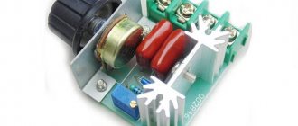
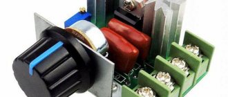
Power regulator on triac BTA 16-600, characteristics and purpose
Welcome to my website! In this article I will talk about the power (voltage) regulator on a triac. It is made on a triac BTA16-600B. Made quite well. Designed for use in household appliances to regulate voltage and power. The voltage can be lowered from 230 to any, for example to 50 volts or 20. Or you can set any other voltage that you need. This is regulated by a blue tuning resistor when a voltmeter is connected.
Input voltage: 220 V. Maximum power: 2000 W. Adjustable voltage: 50-220V AC. Material: plastic, metal. Dimensions: 4.8 cm x 5.5 cm x 2.7 cm.
Functionality check
If we take into account what has already been written in this article, then such a check is not difficult to perform. How to check a triac? This can be done in several ways. The easiest way to check the serviceability is the replacement method. Instead of a suspected triac, we install a known good one, and see how the circuit will work. But usually triacs are checked using a multimeter or tester, sometimes without disconnecting from the circuit. A tester is an old-type pointer multimeter. In addition, there is another way to check, using a toggle switch, a light bulb and a button. Let's look at the last two ways to check the triac in more detail.
Checking with a tester
The triac has three outputs that will need to be ringed in pairs. This is the test. Turn the tester into resistance measurement mode in the kilo-ohm range and set its arrow to zero, connecting the probes to each other. In old pointer instruments this is a necessary operation. It is useful to know which of the tester probes has a positive polarity - this will allow you to determine the type of pn junction associated with the control electrode.
Since the design of triacs can be different, mark the test simulator in some way, in any way, this is just a convention. Then test all three possible pairs of electrodes, changing the polarity of their connection, and write the results in the table. Depending on the condition of the device, and even the type, you will get different results. Checking is easier if you know the type of device in advance (if you lack knowledge and experience, you can confuse it with a transistor). Since the article deals specifically with a triac (triac), we will further assume that we are testing it.
Some typical resistances to test:
- 0 Ohm - breakdown, short circuit;
- 50 ... 100 Ohm - open (forward biased) pn junction;
- 1 ... 10 kOhm - leakage, the semiconductor crystal is damaged;
- 1 MOhm... ∞ - locked (reverse-biased) pn junction or open.
A sign that the triac is working is that there is a pair of pins that, regardless of the polarity of the tester probes, gives signs of a working pn junction, while with the third pin, either of the two shows a very high resistance. The remaining cases show, at a minimum, a very questionable state of the device.
Power regulator circuit
You can connect different devices to this power (voltage) regulator, up to 2000 watts. (but subject to replacing the radiator with a larger one), such as a lamp, a soldering iron for heating control, a drill and other devices where you need to regulate lighting, voltage, speed, temperature. To do this, as I wrote above, you need to smoothly turn the variable (tuning) resistor R2 towards increasing or decreasing the load.
The diagram shows:
Triac BTA16-600B on the radiator, Dinistor DIAC DB3, Capacitor C1 – 0.1 uF 400 V, Variable resistors R1 – 500 K, R2 – multi-turn resistor 2 Mohm R3 – 0.25 watt – 4.7 kOhm, R 4 – 1W -100 Ohm Connection terminals power and load.
What should be noted is that such a power (voltage) regulator is sold with small radiators and there is no paste between the triac and the radiator. When connecting a large load, more than 500 watts, it is better to install a larger radiator and, of course, with paste. The regulator works properly, smoothly reduces and increases the load. In general, it is quite suitable for home purposes. The only thing is that you can strengthen it if you install a higher current triac and a radiator. You can also install resistors of higher power; capacitors will do just fine according to the diagram.
Main parameters: VRRM,V (Peak repeating reverse voltage) 600 IT(RMS) (max.),A (On-state operating current) 16 VDRM (max.),V (Peak repeating on-state voltage) 600 IFSM (max .),A (Peak peak forward current per diode at a temperature of 10 ms) 168 IFT (max.),mA (Minimum gate current) 50 dV/dt,V/µs (Critical rate of rise of voltage in the off state)1000 dI/dt ,A/ms (Critical rate of rise of current in open position) 14 TA,°C (Operating temperature range) from -40 to 125 Case TO-220AB
Purpose and device
Triacs are semiconductor semi-controlled switches that are opened by a current pulse through a control electrode. To close it, you need to interrupt the current in the circuit or apply reverse voltage.
According to the principle of operation, they are similar to thyristors. The only difference is that a triac is two thyristors connected back-to-back. You can see the designation in the diagram below.
By definition, they are often used in relay mode - in simple words they work to “turn on” and “turn off”; by the way, such relays are called semiconductor.
The differences from the electromechanical one are the following: the speed is orders of magnitude higher, there are no contacts, and therefore greater durability. The main condition for long-term operation is to ensure the nominal thermal conditions and load.
A variety of BTA triacs
There are also triacs for 12, 41 amperes. They can withstand heavy loads. I have a homemade power regulator using a VTA triac. You can order a power regulator on a triac here. On my channel for visiting radio amateurs, the videos cover reviews of electrical circuits, power supplies, amplifiers, voltage and current converters, various circuits and constructors made from radio components. Which are assembled at home and are available to every amateur without any problems or difficulties. Order and use for your own purposes to control household appliances.
I installed a larger radiator on my power (voltage) regulator and now it can withstand heavy loads. That's all, subscribe to the channel and leave your comments on what and how you would do with this module.
Subscribe to my channel, I will be glad to have new subscribers, like and comment.
Also watch the video voltage regulator
Application
This type of semiconductor elements was originally intended for use in the manufacturing sector, for example, to control electric motors of machine tools or other devices where continuously variable current control is required. Subsequently, when the technical base made it possible to significantly reduce the size of semiconductors, the scope of application of symmetrical thyristors expanded significantly. Today, these devices are used not only in industrial equipment, but also in many household appliances, for example:
- chargers for car batteries;
- household compressor equipment;
- various types of electric heating devices, ranging from electric ovens to microwaves;
- hand-held electric tools (screwdriver, hammer drill, etc.).
And this is not a complete list.
At one time, simple electronic devices were popular that allowed smooth adjustment of lighting levels. Unfortunately, dimmers based on symmetrical thyristors cannot control energy-saving and LED lamps, so these devices are not relevant now.
Triac power regulator
Simple power regulator for soldering iron (lamp) on MAC97A
A simple power regulator up to 100W can be made from just a few parts. It can be adapted to regulate the temperature of a soldering iron tip, the brightness of a desk lamp, fan speed, etc. The thyristor-based regulator is very large in size and has design flaws and a large circuit. The power regulator on the imported small-sized triac mac97a (600V; 0.6A) can also switch more powerful loads, simple circuit, smooth adjustment, small dimensions.
If a thyristor has an anode and a cathode, then the electrodes of a triac cannot be characterized in this way, because each electrode is both an anode and a cathode at the same time. Unlike a thyristor, which conducts current in only one direction, a triac is capable of conducting current in two directions. This is why the triac works great in AC networks.
Just a simple circuit that characterizes the principle of operation of a triac is our electronic power regulator.
After connecting the device to the network, alternating voltage is supplied to one of the electrodes of the triac. A negative control voltage is supplied to the electrode, which is the control electrode from the diode bridge. When the switching threshold is exceeded, the triac will open and current will flow to the load. At the moment when the voltage at the triac input changes polarity, it will close. Then the process is repeated.
The higher the control voltage level, the faster the triac will turn on and the duration of the pulse on the load will be longer. As the control voltage decreases, the duration of the pulses on the load will be shorter. After the triac, the voltage has a sawtooth shape with an adjustable pulse duration.
In this case, by changing the control voltage we can adjust the brightness of a light bulb or the temperature of the soldering iron tip, as well as the fan speed.
Schematic diagram of the regulator based on the MAC97A6 triac
Description of the operation of the power regulator on a triac
At each half-wave of the mains voltage, capacitor C is charged through the resistance chain R1, R2, when the voltage on C becomes equal to the opening voltage of the dinistor VD1, breakdown and discharge of the capacitor occurs through the control electrode VS1.
The DB3 dinistor is a bidirectional diode (trigger diode), which is specially designed to control a triac or thyristor. In its basic state, the DB3 dinistor does not conduct current through itself (except for a slight leakage current) until a breakdown voltage is applied to it.
At this moment, the dinistor goes into avalanche breakdown mode and exhibits the property of negative resistance. As a result of this, a voltage drop of around 5 volts occurs across the DB3 dinistor, and it begins to pass through itself a current sufficient to open a triac or thyristor.
The current-voltage characteristic (volt-ampere characteristic) diagram of the DB3 dinistor is shown in the figure:
Since this type of semiconductor is a symmetrical dinistor (both of its terminals are anodes), there is no difference how to connect it.
Characteristics of DB3 dinistor
For those who need to regulate a load of more than 100W, below is a similar diagram of a more powerful regulator based on the VT136-600 triac.
Schematic diagram of the regulator based on the BT136-600 triac
The given circuit of the power regulator on a triac is designed for a fairly large load current.
If you do not have the necessary parts and board to assemble a power regulator on a MAC97A6 triac, you can buy a complete kit for assembling it in our store.
Purpose and device
Triacs are semiconductor semi-controlled switches that are opened by a current pulse through a control electrode. To close it, you need to interrupt the current in the circuit or apply reverse voltage.
According to the principle of operation, they are similar to thyristors. The only difference is that a triac is two thyristors connected back-to-back. You can see the designation in the diagram below.
By definition, they are often used in relay mode - in simple words they work to “turn on” and “turn off”; by the way, such relays are called semiconductor.
The differences from the electromechanical one are the following: the speed is orders of magnitude higher, there are no contacts, and therefore greater durability. The main condition for long-term operation is to ensure the nominal thermal conditions and load.
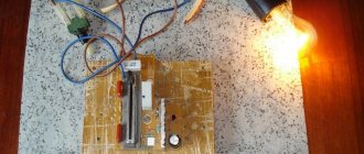
DISCRETE POWER CONTROLLER
Figure 1 – general initial view
On the right side of the top plastic cover there was a hole for the handle of the built-in power regulator, which was not there. By luck, some time later I came across a working copy of the same fireplace. At first glance, the regulator was a rather complex circuit with two thyristors and many very powerful resistors. It made no sense to repeat it, although I have access to almost any Soviet radio components, since it would cost many times more than the version that is manufactured now.
To begin with, the fireplace was connected directly to the network, the current consumption turned out to be 5.6 A, which corresponds to the nameplate power of the fireplace 1.25 kW. But why waste so much energy, especially since it is not cheap, and you don’t always need to turn on the heater at full power. Therefore, it was decided to start searching for a powerful power regulator. In my stash I found a ready-made circuit from a Chinese vacuum cleaner, based on a BTA12-600 triac. The triac, with its rated current of 12 A, suited me perfectly. This regulator was a phase regulator, i.e. This type of regulator does not pass the entire half-wave of the mains sinusoidal voltage, but only part of it, thereby limiting the power supplied to the load. Is the adjustment carried out by opening the triac at the desired phase angle?
Figure 2 – a) usual form of mains voltage; b) voltage supplied through the regulator
Advantages of a phase regulator:
- ease of manufacture - low cost - easy controllability
Flaws:
- with a simple circuit, normal operation is observed only with loads such as incandescent lamps - with a powerful active load, an unpleasant hum (battering) appears, which can occur both in the triac itself and at the load (heating coil) - creates a lot of radio interference - pollutes the electrical network
As a result, after testing the regulator circuit from a vacuum cleaner, rattling of the electric fireplace spiral was detected.
Figure 3 – View inside the fireplace
The spiral looks like a wound wire (I can’t determine the material) on two strips, filled with some kind of heat-resistant hardener to fix it on the edges of the strips. Perhaps the rattling could cause its destruction. Attempts were made to connect the inductor in series with the load, and to bypass the triac with an RC circuit (which is a partial salvation from interference). But none of these measures gave complete relief from noise.
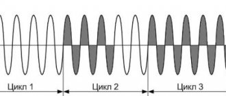
It was decided to use a different type of controller - discrete. Such regulators open the triac for a period of a whole half-wave of voltage, but the number of half-waves passed is limited. For example, in Figure 3, the solid part of the graph is the half-waves that passed through the triac, the dotted part is the half-waves that did not pass through, that is, at that time the triac was closed.
Figure 4 – Principle of discrete regulation
Advantages of discrete controllers:
- less heating of the triac - no sound effects even with a fairly powerful load - no radio interference - no pollution of the electrical network
Flaws:
- voltage surges are possible (at 220V by 4-6 V with a load of 1.25 kW), which can be noticeable on incandescent lamps. This effect is not noticeable on other home appliances.
The identified drawback becomes more noticeable the lower the adjustment limit is set to. At maximum load there are absolutely no surges. As a possible solution to this problem, it is possible to use a voltage stabilizer for incandescent lamps. The following scheme was found on the Internet, which attracted attention with its simplicity and ease of control.
Using a battery and a light bulb
There is an option to test a triac with a simple tester, which is an open single-line circuit with a power source and a test lamp. You will also need an additional power source for testing. Any battery can be used as it, for example type AA with a voltage of 1.5 V.
The details must be called in a certain order. First of all, it is necessary to connect the contacts of the tester with the working contacts of the triac. The control lamp should not light up.