The USB interface began to be widely used about 20 years ago, to be precise, since the spring of 1997. It was then that the universal serial bus was implemented in hardware in many personal computer motherboards. Currently, this type of connecting peripherals to a PC is a standard, versions have been released that have significantly increased the data exchange speed, and new types of connectors have appeared. Let's try to understand the specifications, pinouts and other features of USB.
What are the advantages of Universal Serial Bus?
The introduction of this connection method made it possible:
- Quickly connect various peripheral devices to your PC, from the keyboard to external disk drives.
- Make full use of Plug&Play technology, which simplifies the connection and configuration of peripherals.
- Refusal of a number of outdated interfaces, which had a positive impact on the functionality of computing systems.
- The bus allows not only to transfer data, but also to supply power to connected devices, with a load current limit of 0.5 and 0.9 A for the old and new generations. This made it possible to use USB to charge phones, as well as connect various gadgets (mini fans, lights, etc.).
- It has become possible to manufacture mobile controllers, for example, a USB RJ-45 network card, electronic keys for entering and exiting the system
Charging the battery via Micro USB
In addition, it supplies a 5-volt power supply to charge the battery of wearable gadgets. Since almost all modern lithium batteries have an operating voltage of 3.7 V, the 5 V supplied via Micro-USB is excellent for replenishing energy. True, not directly to the battery, but through the charger converter.
I’m glad that the connector pinout is the same for all smartphone manufacturers - Samsung, LG, Huaway and others. Thus, a 220 V charger-adapter from one phone is most often suitable for charging another without changing the pinout.
- The main advantage of the Micro-USB connector over other types is the ability to connect Plug&Play devices without the need to restart the computer or manually install drivers. Devices can be connected while the computer is running and disconnected without having to press any buttons.
Types of USB connectors - main differences and features
There are three specifications (versions) of this type of connection that are partially compatible with each other:
- The very first version that has become widespread is v 1. It is an improved modification of the previous version (1.0), which practically did not leave the prototype phase due to serious errors in the data transfer protocol. This specification has the following characteristics:
- Dual-mode data transfer at high and low speed (12.0 and 1.50 Mbps, respectively).
- Possibility of connecting more than a hundred different devices (including hubs).
- The maximum cord length is 3.0 and 5.0 m for high and low transfer speeds, respectively.
- The rated bus voltage is 5.0 V, the permissible load current of the connected equipment is 0.5 A.
Today this standard is practically not used due to its low throughput.
- The dominant second specification today... This standard is fully compatible with the previous modification. A distinctive feature is the presence of a high-speed data exchange protocol (up to 480.0 Mbit per second).
A clear demonstration of the advantages of USB 2.0 over other interfaces (transfer speed 60 MB per second, which corresponds to 480 Mbit per second).
Thanks to full hardware compatibility with the younger version, peripheral devices of this standard can be connected to the previous modification. True, the throughput will decrease up to 35-40 times, and in some cases more.
Since these versions are fully compatible, their cables and connectors are identical.
Please note that, despite the bandwidth specified in the specification, the actual data exchange speed in the second generation is somewhat lower (about 30-35 MB per second). This is due to the implementation of the protocol, which leads to delays between data packets. Since modern drives have a read speed four times higher than the throughput of the second modification, that is, it does not meet current requirements.
- The 3rd generation universal bus was developed specifically to solve problems of insufficient bandwidth. According to the specification, this modification is capable of exchanging information at a speed of 5.0 Gbit per second, which is almost three times the reading speed of modern drives. Plugs and sockets of the latest modification are usually marked blue to facilitate identification of belonging to this specification.
USB 3.0 connectors have a characteristic blue color.
Another feature of the third generation is an increase in the rated current to 0.9 A, which allows you to power a number of devices and eliminate the need for separate power supplies for them.
As for compatibility with the previous version, it is partially implemented; this will be discussed in detail below.
Technical characteristics of each model
The first model is USB 1.0. This specification distinguishes two operating modes:
- Low bandwidth.
- With high throughput.
The maximum cable length allowed in this model for the first operating mode is three meters, and for the second operating mode it reaches five meters. If you want to connect several devices, you can connect up to 127 of them.
The technical characteristics of the USB 1.1 model correspond to the first, but all the problems and errors that arose during its use have been corrected. By the way, this is the first model that gained wide popularity
and spread quickly.
The third model is USB 2.0. There are three operating modes for it, where mice, a joystick, gamepads, and a keyboard can be used, as well as video devices and devices that store information.
Classification and pinout
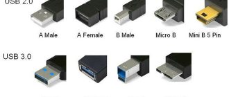
Connectors are usually classified by type, there are only two of them:
- A is a plug connected to the female socket installed on the PC system board or USB hub. Using this type of connection, you can connect a USB flash drive, keyboard, mouse, etc. These connections are fully compatible between the initial version and the second generation. With the latest modification, compatibility is partial, that is, devices and cables from earlier versions can be connected to third-generation sockets, but not vice versa.
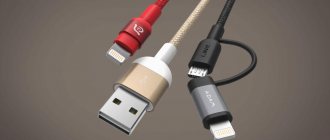
Type A connectors - B – plug for connecting to a socket installed on a peripheral device, for example, a printer. The dimensions of the classic type B do not allow it to be used for connecting small-sized devices (for example, tablets, mobile phones, digital cameras, etc.). To correct the situation, two standard reduced modifications of type B were adopted: mini and micro USB.
Note that such convectors are compatible only between earlier modifications.
Various Type B Connector Models
In addition, there are extension cables for the ports of this interface. At one end there is a type A plug, and at the other there is a socket for it, that is, in fact, a “female” - “male” connection. Such cords can be very useful, for example, to connect a flash drive without crawling under the table to the system unit.
USB Extension Cable
Now let's look at how contacts are wired for each of the types listed above.
Advantages
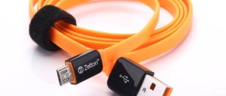
The USB cable with micro plug is distinguished by its increased strength and reliability of the case. In case of improper handling and repair, the contacts may break. Malfunctions are caused by sudden movements when connecting to the port, or by falling of the gadget, especially when the connector hits a hard surface. Sometimes malfunctions occur due to manufacturing defects or improper use.
USB Micro Cable
If soldering is done incorrectly when connecting the cable, failures occur, which are characterized by the following symptoms:
- notifications about hardware errors appear on the gadget’s screen, the device does not find or does not recognize the connection;
- there is no synchronization between connected devices, but charging is carried out;
- The battery icon identifies the charging process, but no actual power is supplied;
- the device does not respond to connection or issues a failure alert;
- There is a short circuit in the power supply or port.
Poor contact may be caused by irregularities that occur between the chain links. Soldering is carried out using pin desoldering. This procedure is called pinout. Each wire is reconnected after stripping, based on color identification.
Do not rush, otherwise you may damage neighboring areas. This pinout allows you to avoid mistakes that lead to equipment failure.
USB 2.0 connector pinout (types A and B)
Since the physical plugs and sockets of early versions 1.1 and 2.0 do not differ from each other, we will present the wiring of the latter.
Figure 6. Wiring the plug and socket of type A connector
Designation:
- A – nest.
- B – plug.
- 1 – power supply +5.0 V.
- 2 and 3 signal wires.
- 4 – mass.
In the figure, the coloring of the contacts is shown according to the colors of the wire, and corresponds to the accepted specification.
Now let's look at the wiring of the classic socket B.
Wiring of plug and socket type B
Designation:
- A – plug connected to the socket on peripheral devices.
- B – socket on a peripheral device.
- 1 – power contact (+5 V).
- 2 and 3 – signal contacts.
- 4 – ground wire contact.
The colors of the contacts correspond to the accepted colors of the wires in the cord.
Functions of the “legs” of the micro-USB connector
The micro-USB connector is used to charge small and portable volatile devices and synchronize data between PCs and gadgets. It consists of five "legs". Two “legs” are separated on opposite sides of the case: one is the positive 5V rating, the second is the negative one. This arrangement reduces the likelihood of breakdown.
Close to the negative leg there is another contact, which can easily break if connected to the port carelessly. If this “leg” is damaged, the cable fails. The battery icon may indicate connection progress, but may not actually charge. Most often, this damage results in the gadget not responding to the plug being connected.
The two remaining “legs” are used for data exchange and synchronization between devices. With their help, you can upload and download files from the gadget to your PC and back, transfer videos, photos, and audio. The work is carried out synchronously. If only one contact is damaged, the second one stops working. Knowing the color pinout allows you to solder the wires correctly and resume the plug’s operation.
Useful tips Connection diagrams Principles of operation of devices Main concepts Meters from Energomer Precautions Incandescent lamps Video instructions for the master Testing with a multimeter
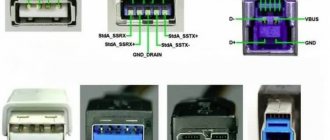
USB 3.0 pinout (types A and B)
In the third generation, peripheral devices are connected via 10 (9 if there is no shielding braid) wires; accordingly, the number of contacts is also increased. But they are located in such a way that it is possible to connect devices of earlier generations. That is, the +5.0 V contacts, GND, D+ and D-, are located in the same way as in the previous version. The wiring for Type A socket is shown in the figure below.
Figure 8. Pinout of Type A connector in USB 3.0
Designation:
- A – plug.
- B – nest.
- 1, 2, 3, 4 – connectors fully correspond to the pinout of the plug for version 2.0 (see B in Fig. 6), the colors of the wires also match.
- 5 (SS_TX-) and 6 (SS_TX+) connectors for data transmission wires via the SUPER_SPEED protocol.
- 7 – ground (GND) for signal wires.
- 8 (SS_RX-) and 9 (SS_RX+) connectors for data receiving wires using the SUPER_SPEED protocol.
The colors in the figure correspond to those generally accepted for this standard.
As mentioned above, a plug from an earlier model can be inserted into the socket of this port; accordingly, the throughput will decrease. As for the plug of the third generation of the universal bus, it is impossible to insert it into the sockets of the early release.
Now let's look at the pinout for the type B socket. Unlike the previous type, such a socket is incompatible with any plug of earlier versions.
Wiring USB 3.0 type B
Designations:
A and B are plug and socket, respectively.
Digital signatures for contacts correspond to the description in Figure 8.
The color is as close as possible to the color markings of the wires in the cord.
Micro USB connector pinout
To begin with, we present the wiring for this specification.
Micro USB v 2.0 connector wiring
As can be seen from the figure, this is a 5 pin connection; both the plug (A) and socket (B) have four contacts. Their purpose and digital and color designation correspond to the accepted standard, which was given above.
Description of the micro USB connector for version 3.0.
For this connection, a characteristically shaped 10 pin connector is used. In fact, it consists of two parts of 5 pin each, and one of them fully corresponds to the previous version of the interface. This implementation is somewhat confusing, especially considering the incompatibility of these types. Probably, the developers planned to make it possible to work with connectors of earlier modifications, but subsequently abandoned this idea or have not yet implemented it.
MicroUSB connector layout for version 3.0
The figure shows the pinout of the plug (A) and the appearance of the micro USB socket (B).
Contacts 1 to 5 fully correspond to the second generation micro connector, the purpose of the other contacts is as follows:
- 6 and 7 – data transmission via high-speed protocol (SS_TX- and SS_TX+, respectively).
- 8 – mass for high-speed information channels.
- 9 and 10 – data reception via high-speed protocol (SS_RX- and SS_RX+, respectively).
Mini USB pinout
This connection option is used only in early versions of the interface; in the third generation this type is not used.
Mini USB connector pinout
As you can see, the wiring of the plug and socket is almost identical to the micro USB, respectively, the color scheme of the wires and the contact numbers are also the same. Actually, the differences are only in shape and size.
In this article we have presented only standard types of connections; many manufacturers of digital equipment practice introducing their own standards; there you can find connectors for 7 pin, 8 pin, etc. This introduces certain difficulties, especially when the question arises of finding a charger for a mobile phone. It should also be noted that products are in no hurry to tell how the USB pinout is done in such contactors. But, as a rule, this information is easy to find on thematic forums.