There is a situation when a transformer does not have a winding for the required voltage or current, but there are many different windings. What to do?
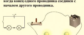
To increase the voltage, the windings can be connected in series. In this case, the total voltage will be equal to the sum of the voltages of all windings. The maximum current will be equal to the smallest of the rated currents of all these windings.
The windings must be phased, otherwise the voltages in them may not be added, but subtracted (you can
work in such a situation, but the efficiency of the transformer will decrease). This is done like this: the first and second windings are connected in series, and an alternating current voltmeter is connected to their ends (Fig. 16).
The voltmeter should show the sum of the voltages of windings 1 and 2 (this is in-phase, or consonant connection of the windings). If the voltmeter readings are less (in the case of antiphase or counter-connection, it will show the voltage difference between the windings), the terminals of winding 2 must be swapped. In the case when a larger number of windings are connected in series, then everything is repeated, with the role of winding 1 being played by the already connected windings, and the role of winding 2 by the newly connected winding.
In Fig. 16, a dot near the winding indicates its conditional beginning. It has the following meaning: if at the terminal with the point of the primary winding there is a positive half-cycle of voltage (roughly speaking, “plus”), then at the terminals with the point of all secondary windings there is also a “plus” at this moment. Therefore, knowing the conditional beginnings of the windings, you can immediately connect all the windings in phase. Unfortunately, the beginnings of the windings are usually not marked on the transformer itself.
If a transformer has many identical secondary windings with a small current, then in theory they can be connected in parallel, then their total current will be equal to the sum of the currents of the individual windings.
In fact, this is a very “subtle” question. In life, it almost never happens that two windings are exactly the same. Although there is a tiny difference in their voltages, there is. And inside the parallel windings, equalizing currents can arise, sometimes small and sometimes large. It may turn out that the transformer gets very hot, but produces almost no current outside. But it also happens that manufacturers wind a transformer in several wires at the same time. Then the windings turn out to be almost exactly the same and such windings can be connected in parallel (although GOST 14233-84 “Power transformers for household equipment” gives a tolerance for the asymmetry of windings connected in parallel, up to 3% of the winding voltage - this is a rather large mismatch!). In this case, it is very important to correctly phase the windings, otherwise there will be a short circuit. You just need to be absolutely sure that the windings are the same. So let's use this rule to be safe:
If the manufacturer clearly indicates that the transformer windings can be connected in parallel, then it is possible. If there is no such explicit indication, then it is impossible.
How to phase the windings correctly? The beginning of all the windings is connected together - this will be the beginning of the common winding. The end of the common winding will be made up of the ends of all windings connected together.
If the beginnings and ends of the windings are unknown, then first connect one wire from one winding and one from the other. Apply power to the transformer and measure the voltage between the remaining ends of these windings (Figure 17).
If the voltage between them is equal to twice the voltage of each winding, then the ends of one of the windings must be swapped. Apply power again and measure the voltage again. If it is equal to zero, then everything is OK, connect the ends between which you measured the voltage and use it. If the voltage is not zero, then the windings are different and cannot be parallelized!
And if the voltage on two windings does not turn out
zero, but very close to zero? Let's look at an example. The resistance of the secondary winding of a 75VA 2x28V toroidal transformer is approximately 0.5 Ohms. Let's say we want to get such a winding from two, each of which is designed for half the current. Then the resistance of each winding is twice as high and will be equal to 1 Ohm. From the point of view of equalizing currents, the windings are connected in series (which means the total resistance doubles) and the voltage difference between the windings is applied to them. Let's say this voltage difference is 0.5 volts. Then the equalizing current will be
2. If the voltmeter shows the difference in winding voltages exactly equal to zero, this means that both the voltage shapes of the windings and their values are the same (which in itself is a rare phenomenon). But who can guarantee that when the voltage in the network changes, or the current consumed by the load changes, the shapes of the currents will remain the same? This does not always happen even with transformers of the same type (due to the variation in the properties of steel, they may be saturated slightly differently), and for transformers of different types this is generally unrealistic.
Therefore, let's not take risks and let's not create possible problems for ourselves by connecting the windings of different transformers in parallel!
Current surge when turning on the transformer. When a transformer is connected to the network, even at idle, a surge of current occurs (inrush current resulting from a transient process in the transformer), which can exceed the rated one tens of times. The duration of the starting current usually does not exceed 0.02...0.03 seconds, so it does not lead to overheating of the windings. However, at this moment, significant electromagnetic forces act on the winding conductors, which can move poorly secured turns. Over time, the turns become loose and the acoustic noise of the transformer increases.
Another unpleasant consequence of the inrush current is the blowing of the fuse in the primary winding circuit.
The magnitude of the starting current is determined both by the moment of switching on (in relation to the initial phase of the mains voltage) and by the parameters of the transformer. In particular, increasing the number of turns of the primary winding reduces the inrush current, which once again speaks in favor of the use of transformers with reduced operating induction. Conversely, a transformer operating close to saturation may have a very large inrush current when turned on.
Transformers with reduced operating induction. There is an opinion (quite justified) that good results are obtained by using transformers with reduced induction in amplifiers, operating in an almost linear section of the magnetization curve (end of section A - beginning of section B in Fig. 9). Indeed, a decrease in induction reduces leakage fluxes, and therefore the magnetic fields of the transformer, and also reduces the inrush current. This is achieved by increasing the number of turns in the windings by 1.2...1.3 times higher than the nominal one. Reducing stray fields reduces the inductance of the windings, but due to an increase in the length of the wire, their active resistance increases, so the voltage drops under load practically do not change, but the heating of the windings increases. To normalize heating, the power of the transformer is increased, increasing the diameter of the winding wires.
Thus, in order to obtain a transformer with reduced operating induction, it is necessary to manufacture a transformer with a power of 1.3...1.5 times more than required, all windings of which are designed for a voltage of 1.2...1.3 times more than required.
It should be noted that in this case only the operation of the transformer itself improves; this does not affect the amplifier in any way (unless the magnetic fields of the transformer act on the amplifier, but this must be strived for in any case). Therefore, the cost of such a special transformer almost never pays off (except for very high quality equipment, where the use of such a transformer is not only justified, but often simply necessary), and in the designs of beginning radio amateurs - for sure. Therefore, it makes sense to use a “low-induction” transformer if you already have one, but if you don’t have one, then there’s no need.
Core magnetization with direct current. A transformer is a device designed to operate on alternating current (and only its own frequency, or one close to it - if the current frequency is very different from the rated one, it may work worse or not work at all). It does not convert direct current, because the EMF in the windings is induced only by a changing magnetic field, which is obtained if the current is alternating. And direct current is not affected by the inductance of the windings. Therefore, if 220 volts of direct current is supplied to the transformer, the transformer will burn out - the active resistance of the primary winding is small, and the current will be huge.
What happens if direct current still flows through the winding? On alternating current, even very high winding currents practically do not change the operating magnetic flux, since the influences of the primary and secondary windings are mutually compensated. At direct current, there is no interaction between the windings and mutual compensation of currents. Direct current will create an uncompensated magnetic field, which will magnetize the core, changing the induction in it. If this field is large enough, then the core will begin to saturate with all the ensuing consequences.
So the appearance of direct current (of appreciable magnitude) in the transformer should be avoided. An exception is the output transformers of lamp technology - they have a gap in the core to prevent saturation. But even in this case, the transformer is not very comfortable to operate.
There were several transformers lying idle, and one of them (Soviet TSA-30-1
, 30 W) I decided to use it for a universal power supply.
Since its original windings did not suit me (mainly in terms of permissible current), I decided to remove all its secondary windings and wind my own. The process was accompanied by many “discoveries” and puzzling questions, in the process of solving which many useful details were collected that I wanted to share with newcomers to this business, like me.
The article contains a video with details of some of the stages.
Where I was unfairly lucky here:
- There was free time and no one interfered.
- There were a lot of different old stocks, incl. copper wire of the required length.
- There is a lot of information on the Internet (especially regarding theory).
Zarathustra forgave me...
Video of transformer rewinding
Time of different stages of this video:
26 min 28 sec
- foil screen between primary and secondary
27 min 52 sec
- how to correctly connect the windings in series
36 min 43 sec
- how to find out the direction of turns using a battery and a multimeter
44 min 14 sec
- calculation and winding of a new secondary winding
1 hour 24 minutes 20 seconds
— mains voltage sag and other losses
1 h 30 min 01 sec
— no-load current
1 hour 32 minutes 14 seconds
- aluminum soldering
1 hour 33 minutes 42 seconds
- result
No-load current
If everything is done correctly and the transformer core was assembled (at the factory) with high quality, then the no-load current (current of the primary winding, with the secondary winding completely disconnected from the load) should be within acceptable limits.
In my case, this current was 27 mA, which is just an excellent indicator.
The ammeter must be connected to the break in the network cable connected to the primary winding and, preferably connecting the multimeter probes, connect the transformer to the network. Then disconnect the probes and observe the readings. It is necessary to connect the probes before connecting them to the network to avoid failure of the multimeter, because The transformer may have a large starting current (tens of times higher than the rated current).
Study of a modified transformer
Transformer TSA-30-1
turned out to be wound with aluminum wire (the letter “A” just means aluminum).
Fortunately, there was enough information about him on the Internet, although the reality did not coincide with the passport found for him. According to the passport, one of the windings was supposed to be copper (the PEV-1 wire does not have the letter “A” in the name like the others - PEVA), and I planned not to touch it, but during the work it turned out that this winding was also aluminum . So I deleted it too. Those. Only the primary winding remained intact.
Aluminum foil screen
During the disassembly process, out of curiosity, I unrolled some paraffin paper over the primary winding and wanted to look at it, and came across one turn of foil that was present between the primary winding and the secondary. This roll of foil overlapped with the paper, i.e. it did not close, and only one of the ends was spot welded to the body with a piece of copper wire. This separation is used as a shield against interference, although there is debate about its effectiveness. The transformer is Soviet and the screen was installed at the manufacturer - I did not touch it.
Direction of turns
The turns on the transformer were wound on different coils (left and right) in exactly the same way (not mirrored, but exactly the same). Later it became clear that such winding was made solely for convenience during the subsequent serial connection of windings from different coils. Apparently, for the same reason, the direction of different secondary windings alternates. In this case, it is simply more convenient to place the jumpers between the windings in a series connection on one side.
Metal terminals
The terminals of this transformer are very difficult to solder and tin, since they do not appear to be made of copper. Copper, the better you warm it up, the better it is soldered, and for steel (?) terminals, heating leads to the solder rolling into a ball and flowing from the terminal to the soldering iron tip. It is necessary to catch one of the initial moments of warming up so that the solder remains on the terminal in an acceptable form.
In the transformer under study it was doubly difficult, because aluminum was soldered to the metal terminals. phosphoric acid for soldering.
followed by washing with water and drying on a radiator.
Primary winding
This transformer has two coils, and each winding is divided into two equal parts, which are wound on each of the two coils, with a series connection. It is believed that this way the efficiency is higher and the load is more uniform.
The primary winding consists of two 110v on each coil, connected in series with a jumper. In addition, a small additional winding is connected in series to each of the windings, which I disconnected and used for my own purposes (thus turning it into a secondary winding). The voltage of this additional pair is about 36v (at 230v in the network).
Connection diagram for the meter via current transformers
Installation of an electric meter is carried out in accordance with the basic rules and requirements for the device connection diagram. The meter is installed at a temperature of not lower than 5°C.
Energy metering devices, along with any other electronics, are extremely difficult to withstand low-temperature exposure. Installing an electric meter on the street will require the construction of a special sealed insulated cabinet. The metering device is fixed at a height of no more than 100-170 cm, which facilitates operation and maintenance.
Connection diagram for MERCURY meters
For self-installation, you need to purchase an electric meter and panel, automatic insulating materials, cables and fasteners, DIN rails, and also prepare a set of installation tools.
Connecting a single-phase device
When installing a single-phase metering device, special attention must be paid to the order of connecting cables to the terminal elements:
- The phase wire is connected to the first terminal. The cable being inserted is most often white, brown or black in color;
- The second terminal is used to connect the phase wire experiencing the power load. This cable is usually white, brown or black;
- The third terminal is where the “zero” electrical wire is connected. This input cable has blue or bluish-blue markings;
- the fourth terminal is connected to the neutral wire, which has a blue or bluish-blue color.
Connecting a single-phase device
There is no need to provide grounding protection for the installed and connected electrical metering device.
It should be noted that additional connection sections on a single-phase electric meter are auxiliary and provide operational efficiency or automation of metering of electricity used.
Connection diagram for a three-phase meter via current transformers
Three-phase electricity metering devices are usually equipped with a DIN rail, two types of panels that cover the plug-in terminals, as well as a manual and seals. Self-installation technology:
- installation on a DIN rail of an electrical panel of an input machine and a three-phase electricity meter;
- lowering the clamps on the reverse side of the three-phase energy metering device, followed by installing and raising the clamps;
- connecting the input circuit breaker with the necessary input terminals on the electric meter, in accordance with the connection diagram.
Installation diagram of a three-phase meter
It is convenient to use conductors made of copper wires, the cross-section of which is no less than the standard dimensions of the input cable.
When directly connecting a three-phase electric meter, without the use of input automation, the “phase” and “zero” wires are simultaneously connected to the corresponding terminals of the device.
Calculation of the secondary winding of the transformer
The main mistake I made was calculating the secondary winding based on the voltage in the 220v network. Meanwhile, the network voltage during peak loads can drop to 185v - this is almost 20% lower than required! Therefore, when calculating the secondary winding, we must proceed from this indicator - not 220, but for example 180. Otherwise, you can seriously miscalculate.
When calculating the voltage in the power supply transformer, the following should be taken into account:
- Minimum network voltage ~180 V
- Voltage drop across the diode bridge is more than 2 V
- Voltage drop across the stabilizer - for example 3 V
- Voltage drop on the secondary windings with increasing load current (multiply by an average of 1.02 - 1.06, depending on the maximum current)
The figure below shows the voltage on one element of the KBU801
at a current of 8 A it reaches 1.08 V. I.e. across the entire bridge the voltage drop will be more than 2 V (click to enlarge).
To clarify the number of turns per volt in the secondary winding, you can make a temporary control winding
(for example, 10 turns) and measure the voltage it produces (be sure to check the voltage in the network!). Then divide these 10 (turns) by the resulting voltage. This gives us the number of turns per volt.
IMPORTANT!
It is necessary to divide the turns of the control winding by its voltage, and not vice versa!
Example
.
A supply voltage of 20 V with a maximum constant current of 2 A is required.
A rough estimate looks something like this:
20 + 3 = 23 V (voltage drop across the stabilizer)
23 + 2.2 = 25.2 V (voltage drop across the diode bridge)
25.2 / 1.41 = ~17.3 V (we convert the DC voltage after the diode bridge with a capacitor into the required secondary variable)
17.3 * 1.06 = ~18.4 V (we take into account the voltage drop in the winding at maximum load current)
If we have, for example, 4.4 turns per volt at an ideal ~220 V, then at a voltage of ~180 V in the network, we will need
18.4 * 4.4 = 81 turns (for ideal voltage ~220 V)
81 * (220/180) = 99 turns (for peak voltage drop up to ~180 V)
Those. at ~220 V in the network, the secondary winding containing 99 turns will produce about ~22.5 V (and if the network drops to ~180 V, the required ~18.4 V)
Winding
I wound four parallel wires at the same time. As a result, I got four windings on each coil in each row. This number of windings makes it possible, by connecting them in series (or parallel), to combine the required voltage (and current).
For a laboratory power supply used as a work tool, this is the most convenient option.
IMPORTANT!
For a transformer with an “O” shaped core, with two coils on the right and left (such as the one discussed in this article), it is best to divide each winding into two (identical) ones, wound on different coils and connected in series. In this case, the efficiency will be higher.
BY THE WAY
when laying on the frame, it is advisable to slightly bend the wire outward before each bend at the corners, so that the turns do not then move away from the frame, forming a gap in which the winding density deteriorates. I additionally pressed down the wire with a pine block after each bend on the frame.
Calculation of wire length.
Before winding, it is necessary to measure the width of the frame and the width of the window between the coil frames (or frame and core). After this, you need to calculate the length of the wire and take into account its diameter (with varnish insulation!). If winding occurs without disassembling the core, by threading the wire through the window, then a piece/pieces of wire of the required length will need to be “bitten off” in advance, so it is important not to make a mistake. If the wire is thin enough (for example, less than 0.5 mm) and long, then it makes sense to make a thin shuttle on which to wind the wire of the required length - this will make it easier to drag it through the window.
Here, for example, the internal length of the frame was 54 mm, and expecting to lay 52 turns of wire with a diameter of 1 mm, I did not guess - I had to partially overlap the last half turn (apparently I did not take into account the thickness of the varnish insulation). See the picture (click to enlarge):
When calculating the capabilities of a window, you need to take into account the total thickness of the insulating pads made of paper or varnished fabric between the windings.
To accurately calculate the required length, you need to make a control turn and measure its length. At the same time, in each next row the turn will be a little longer (the thickness of the bottom row and the thickness of the inter-row insulating spacer will affect). You need to understand that, for example, with 50 turns, a length error of one millimeter per turn will give an error of 5 cm at 50 turns. You also need to take into account the margin for conclusions (I added 10 cm on each side to the total length of the pieces, i.e. only 20 cm - this was enough for both conclusions and a possible error).
Direction of turns
I had difficulty finding information about the direction of the winding turns - for this I had to refresh my school physics course (the gimlet rule, etc.). Although this question inevitably arises for a beginner.
The main rule is that the direction of the winding turns does not matter
... as long as there is a need to connect the windings to each other (series or parallel), or in the case of using a transformer in some devices where the signal phase is important.
It doesn’t matter in which direction you wind the turns - what matters is how the windings are then connected
Series connection of windings
When connecting the windings of a transformer in series, you need to mentally imagine that one winding is a continuation of the other, and the point of their connection is a break in a single winding
, in which
the direction of rotation of
the turns around the core remains unchanged (and of course cannot turn in the opposite direction!).
In this case, any terminal of the winding can be the beginning or the end, and the direction of rotation itself can be any. The main thing is that this direction remains the same for the connected windings.
In this case, the movement of the connected windings from top to bottom of the coil or from bottom to top does not matter (see the figure - enlarged by clicking the mouse).
In transformers in which the core is shaped like the letter “O” and the coils are wound on two frames on the right and left, the same rules apply. But for ease of understanding, you can mentally “tear” the core (from above or below), and imagine that it is straightened into one rod - this will make it easier to understand how one winding passes into another while maintaining the direction of rotation of the turns (clockwise or counterclockwise) . See the picture below (the picture can be enlarged by clicking the mouse).
Parallel connection of windings
When connecting in parallel, the length of the wire in the windings is important.
Even with the same number of turns, different windings may have different wire lengths (the winding that is closer to the middle will be shorter, and the one further away will be longer). As a result, cross-flows
.
If parallel connection of the windings is assumed, then it is better to wind them simultaneously in two (three, four...) wires. Then they will be the same length, which will eliminate cross-flows as much as possible during their further parallel connection.
Winding several wires is also used in the absence of a wire of the required cross-section (a large cross-section is collected with several smaller wires).
Checking the direction of turns using a battery and a multimeter
If you have a transformer in which you need to connect two windings in series, but the direction of the turns is not visible or known, you can apply a DC pulse from a battery to one of the windings, observing the voltage surge on the other winding.
When the voltage surge at the moment of connecting the battery on the multimeter (on the second winding) is in “+”, then the connection points of the windings will be any “+” and “-” of different windings (for example, “+” of the multimeter and “-” of the battery, or vice versa) . The other two ends will be the outputs of these windings after connection (see figure - click to enlarge).
Direction of turns on different coils
I repeat - the direction of winding is not important, it is the connection of the windings that is important.
There is one “but” though. If we talk about convenience, then on this type of transformer (with a core in the shape of the letter “O” and two coils), it is more convenient to wind the right and left coils in the same way (not mirrored, but identically). In this case, it will be more convenient to install jumpers when connecting two windings in series on different coils - the jumpers will be on one side, and not across the entire frame from top to bottom.
See the picture (to enlarge, click on the picture):
Serial and parallel connection of windings.
There is a situation when a transformer does not have a winding for the required voltage or current, but there are many different windings. What to do?
To increase the voltage, the windings can be connected in series. In this case, the total voltage will be equal to the sum of the voltages of all windings. The maximum current will be equal to the smallest of the rated currents of all these windings.
The windings must be phased, otherwise the voltages in them may not be added, but subtracted (you can
work in such a situation, but the efficiency of the transformer will decrease). This is done like this: the first and second windings are connected in series, and an alternating current voltmeter is connected to their ends (Fig. 16).
The voltmeter should show the sum of the voltages of windings 1 and 2 (this is in-phase, or consonant connection of the windings). If the voltmeter readings are less (in the case of antiphase or counter-connection, it will show the voltage difference between the windings), the terminals of winding 2 must be swapped. In the case when a larger number of windings are connected in series, then everything is repeated, with the role of winding 1 being played by the already connected windings, and the role of winding 2 by the newly connected winding.
In Fig. 16, a dot near the winding indicates its conditional beginning. It has the following meaning: if at the terminal with the point of the primary winding there is a positive half-cycle of voltage (roughly speaking, “plus”), then at the terminals with the point of all secondary windings there is also a “plus” at this moment. Therefore, knowing the conditional beginnings of the windings, you can immediately connect all the windings in phase. Unfortunately, the beginnings of the windings are usually not marked on the transformer itself.
If a transformer has many identical secondary windings with a small current, then in theory they can be connected in parallel, then their total current will be equal to the sum of the currents of the individual windings.
In fact, this is a very “subtle” question. In life, it almost never happens that two windings are exactly the same. Although there is a tiny difference in their voltages, there is. And inside the parallel windings, equalizing currents can arise, sometimes small and sometimes large. It may turn out that the transformer gets very hot, but produces almost no current outside. But it also happens that manufacturers wind a transformer in several wires at the same time. Then the windings turn out to be almost exactly the same and such windings can be connected in parallel (although GOST 14233-84 “Power transformers for household equipment” gives a tolerance for the asymmetry of windings connected in parallel, up to 3% of the winding voltage - this is a rather large mismatch!). In this case, it is very important to correctly phase the windings, otherwise there will be a short circuit. You just need to be absolutely sure that the windings are the same. So let's use this rule to be safe:
If the manufacturer clearly indicates that the transformer windings can be connected in parallel, then it is possible. If there is no such explicit indication, then it is impossible.
How to phase the windings correctly? The beginning of all the windings is connected together - this will be the beginning of the common winding. The end of the common winding will be made up of the ends of all windings connected together.
If the beginnings and ends of the windings are unknown, then first connect one wire from one winding and one from the other. Apply power to the transformer and measure the voltage between the remaining ends of these windings (Figure 17).
If the voltage between them is equal to twice the voltage of each winding, then the ends of one of the windings must be swapped. Apply power again and measure the voltage again. If it is equal to zero, then everything is OK, connect the ends between which you measured the voltage and use it. If the voltage is not zero, then the windings are different and cannot be parallelized!
And if the voltage on two windings does not turn out
Rice. 17
zero, but very close to zero? Let's look at an example. The resistance of the secondary winding of a 75VA 2x28V toroidal transformer is approximately 0.5 Ohms. Let's say we want to get such a winding from two, each of which is designed for half the current. Then the resistance of each winding is twice as high and will be equal to 1 Ohm. From the point of view of equalizing currents, the windings are connected in series (which means the total resistance doubles) and the voltage difference between the windings is applied to them. Let's say this voltage difference is 0.5 volts. Then the equalizing current will be
2. If the voltmeter shows the difference in winding voltages exactly equal to zero, this means that both the voltage shapes of the windings and their values are the same (which in itself is a rare phenomenon). But who can guarantee that when the voltage in the network changes, or the current consumed by the load changes, the shapes of the currents will remain the same? This does not always happen even with transformers of the same type (due to the variation in the properties of steel, they may be saturated slightly differently), and for transformers of different types this is generally unrealistic.
Therefore, let's not take risks and let's not create possible problems for ourselves by connecting the windings of different transformers in parallel!
Current surge when turning on the transformer. When a transformer is connected to the network, even at idle, a surge of current occurs (inrush current resulting from a transient process in the transformer), which can exceed the rated one tens of times. The duration of the starting current usually does not exceed 0.02...0.03 seconds, so it does not lead to overheating of the windings. However, at this moment, significant electromagnetic forces act on the winding conductors, which can move poorly secured turns. Over time, the turns become loose and the acoustic noise of the transformer increases.
Another unpleasant consequence of the inrush current is the blowing of the fuse in the primary winding circuit.
The magnitude of the starting current is determined both by the moment of switching on (in relation to the initial phase of the mains voltage) and by the parameters of the transformer. In particular, increasing the number of turns of the primary winding reduces the inrush current, which once again speaks in favor of the use of transformers with reduced operating induction. Conversely, a transformer operating close to saturation may have a very large inrush current when turned on.
Transformers with reduced operating induction. There is an opinion (quite justified) that good results are obtained by using transformers with reduced induction in amplifiers, operating in an almost linear section of the magnetization curve (end of section A - beginning of section B in Fig. 9). Indeed, a decrease in induction reduces leakage fluxes, and therefore the magnetic fields of the transformer, and also reduces the inrush current. This is achieved by increasing the number of turns in the windings by 1.2...1.3 times higher than the nominal one. Reducing stray fields reduces the inductance of the windings, but due to an increase in the length of the wire, their active resistance increases, so the voltage drops under load practically do not change, but the heating of the windings increases. To normalize heating, the power of the transformer is increased, increasing the diameter of the winding wires.
Thus, in order to obtain a transformer with reduced operating induction, it is necessary to manufacture a transformer with a power of 1.3...1.5 times more than required, all windings of which are designed for a voltage of 1.2...1.3 times more than required.
It should be noted that in this case only the operation of the transformer itself improves; this does not affect the amplifier in any way (unless the magnetic fields of the transformer act on the amplifier, but this must be strived for in any case). Therefore, the cost of such a special transformer almost never pays off (except for very high quality equipment, where the use of such a transformer is not only justified, but often simply necessary), and in the designs of beginning radio amateurs - for sure. Therefore, it makes sense to use a “low-induction” transformer if you already have one, but if you don’t have one, then there’s no need.
Core magnetization with direct current. A transformer is a device designed to operate on alternating current (and only its own frequency, or one close to it - if the current frequency is very different from the rated one, it may work worse or not work at all). It does not convert direct current, because the EMF in the windings is induced only by a changing magnetic field, which is obtained if the current is alternating. And direct current is not affected by the inductance of the windings. Therefore, if 220 volts of direct current is supplied to the transformer, the transformer will burn out - the active resistance of the primary winding is small, and the current will be huge.
What happens if direct current still flows through the winding? On alternating current, even very high winding currents practically do not change the operating magnetic flux, since the influences of the primary and secondary windings are mutually compensated. At direct current, there is no interaction between the windings and mutual compensation of currents. Direct current will create an uncompensated magnetic field, which will magnetize the core, changing the induction in it. If this field is large enough, then the core will begin to saturate with all the ensuing consequences.
So the appearance of direct current (of appreciable magnitude) in the transformer should be avoided. An exception is the output transformers of lamp technology - they have a gap in the core to prevent saturation. But even in this case, the transformer is not very comfortable to operate.
Source: Rogov I.E. Design of power supplies for audio amplifiers. – Moscow: Infra-Engineering, 2011. – 160 p.
Tweet Like
- Previous post: Installing capacitors on the amplifier board
- Next entry: DEVICE FOR ADJUSTING DIGITAL DEVICES
- What is the difference between current and voltage? (2)
- Current and Voltage Relationship (0)
- POWER SUPPLY FOR CAR RADIO (0)
- BATTERY CHARGER (0)
- LITHIUM-NON CELL CHARGER CHARGER CONTROLLER (0)
- BATTERY CHARGING CURRENT LIMITER (0)
- BATTERY VOLTAGE INDICATOR SIMPLE CIRCUIT (0)


