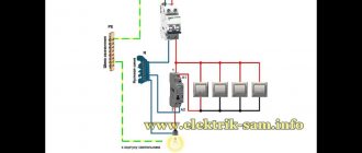
Connection diagram for a 220V magnetic starter
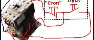
Electric current is supplied to the magnetic coil KM 1 through a thermal relay and terminals connected in a chain of buttons SB2 for turning on - “start” and SB1 for stopping - “stop”. When we press “start”, electric current flows to the coil. At the same time, the starter core attracts the armature, resulting in the closure of the moving power contacts, after which voltage is supplied to the load.
When “start” is released, the circuit does not open, since the KM1 block contact with closed magnetic contacts is connected parallel to this button. Thanks to this, phase voltage L3 is supplied to the coil. When you press “stop,” the power is turned off, the moving contacts return to their original position, which leads to de-energization of the load. The same processes occur when the thermal relay P operates - a break in the zero N supplying the coil is ensured.
How to connect a three-phase motor via a magnetic starter
Power supply 380 V (three phases) is carried out in the same way, only there will be more power wires.
The contactor includes not one, but three phase lines. In this case, the control button is connected according to a similar circuit (as in the single-phase case).
The illustration shows a starter with a 380 V solenoid control coil. The control circuit is switched between any two phases. For safety, there is a thermal relay, the sensors of which can be located on one or several phase wires.
How to connect a 3-phase contactor with a 220 V starter winding? The circuit is similar, only the control circuit is switched between any of the phases and the neutral wire. The thermal relay works just as accurately, since its mechanism is tied to the temperature of the power cables.
Overview of options
In manual mode, activation is carried out from a push-button station. The start button opens the contact to close, and the stop button works to open. The connection diagram for a self-retaining magnetic starter is as follows:
Let's consider the operation of the on and off circuits of a magnetic contactor. A push-button station of two buttons, when you press START, the phase comes from the network through the STOP contacts, the circuit is assembled, the starter retracts and closes the contacts, including the additional NO, which is parallel to the START button. Now, if you release it, the magnetic starter continues to operate until the voltage disappears or the thermal relay P for motor protection is triggered. When STOP is pressed, the circuit is broken, the contactor returns to its original position and the contacts open. Depending on the purpose, the power supply to the coil can be 220V (phase and zero) or 380V (two phases), the operating principle of the control circuits does not change. Switching on a three-phase electric motor with a thermal relay through a push-button station looks like this:
In the end it looks something like this, in the picture:
If you want to connect a three-phase motor through a magnetic starter with a 220-volt coil, you need to make the switch according to the following wiring diagram:
Using three buttons on the control panel, you can organize the reverse rotation of the electric motor.
If you look closely, you can see that it consists of two elements of the previous diagram. When you press START, the KM1 contactor turns on, closing the NO KM1 contacts, becoming self-retaining, and opening the NC KM1, excluding the possibility of turning on the KM2 contactor. When you press the STOP button, the chain is disassembled. Another interesting element of the three-phase reversible connection circuit is the power section.
On the KM2 contactor, phases L1 are replaced by L3, and L3 by L1, thus changing the direction of rotation of the electric motor. In principle, this circuitry for controlling three-phase and single-phase loads completely covers household needs and is easy to understand. You can also connect additional automation elements, protection, limiters. They all need to be considered separately for each specific device.
Using the above diagram for connecting a magnetic starter, you can organize the opening of a garage door by introducing additional limit switches into the circuit, using NC contacts in series with NC KM1 and NC KM2, limiting the movement of the mechanism.
Push-button post: purpose and diagram
Push-button post
— designed for switching electrical control circuits of alternating current voltage up to 660 V, frequency 50 and 60 Hz and direct current voltage up to 440 V, and/or supplying control signals, both locally and remotely; used for remote control of various mechanisms and electrical machines. This is a simple product, consisting of a minimum number of parts, but with a very important function - issuing commands and indicating their execution.
The use of push-button posts is quite diverse and, accordingly, it has different types and designs. Example: control station for a hoist (it would be more correct, of course, to call it “control panel”) Fig.
1 . Using this type of starter, the operation of various traction mechanisms is controlled. These are mainly crane, elevator escalator, beams, etc.
However, the topic of this article will be a standard push-button station for controlling various power devices (mainly various electric motors). “Start-Stop” push-button post, I’ll immediately note that the circuit is applicable not only to magnetic starters but also to any type of relay. So, what is a “button post”? The “button post” structurally consists of a housing and two buttons “Start” and “Stop”. The appearance of buttons for push-button posts is shown in Fig. 1
.
Figure 2
shows the body of the push-button post.
- Both buttons are without fixed position.
- The “Start” button (usually green and may be backlit when turned on) has normally open contacts and is designed to turn on the CM;
- The “Stop” button (usually red) has normally closed contacts and is designed to relieve voltage from the CM;
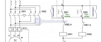
The on-off circuit is shown in Fig. 4
. nothing complicated: when contacts SB1.1 are closed, voltage is supplied to the coil of the contactor KM1 and it is activated, while the contacts SB1.1 of the “Start” button are blocked by the normally open contacts (NO) KM1.4 of the contactor KM1. That's it, the power contacts of the KM1 contactor are closed and voltage is supplied to the power plant. You can release the “Start” button and the power unit will remain energized (will not turn off), since the KM1.4 contacts connected in parallel to the “Start” button are closed and the KM1 starter coil is constantly on. It turns out that after releasing the “Start” button, the phase continues to flow to the coil of the magnetic starter, but through its own pair of contacts KM1.4. To stop the mechanism, use the “Stop” button; when it is pressed, the contacts ST2 open, the voltage from the coil of the contactor KM1 is removed, its contacts KM1.4 open and at the same time unlocking, thereby unlocking the contacts of the “Start” button, the engine is stopped. In Figure 5, the arrow shows the movement of phase “L3” (any of the phases can be selected arbitrarily to power the magnetic contactor coil).
There may be several switching points for a particular system (for example, a ventilation system...). The connection diagram for several push-button posts is shown in Fig. 6
.
With such a switching circuit, the “executive” magnetic contactor (KM 1) can be either turned on or off from any of the “posts”; in such a circuit, it is of course desirable to backlight the start button so that the state of the system can be seen from any of the posts. As you understand, dear reader, the “Start” and “Stop” buttons provide both local (from the control and automation panel) and remote control of the magnetic starter, and therefore the load it switches. Moreover, instead of a motor, you can connect any load, for example, a powerful heating element.
Well, that's all, if you have any questions, use our email
.
Let's try to answer them competently. In the subject line of the email, write: “Irrigation systems.” PS
please do not ask questions that will be answered: “read the article carefully.”
We connect the magnetic starter via a push-button station, the “Start” and “Stop” buttons. For those who read electrical diagrams and can imagine how a circuit works in dynamics, connecting a magnetic starter will not be difficult. The site has repeatedly received requests to suggest how to connect the starter to an engine with start-stop buttons to a 220V network.
I will try to explain literally in my fingers what goes where and why. It is difficult to understand the wiring diagram at first glance. Everything will be clear when you carefully study the circuit, but not all at once, but piece by piece, element by element, asking yourself what role this contact or element plays in the circuit.
At the same time, studying the circuit, find, for example, the control coil of a magnetic starter and its contact terminals. Find power contacts on the starter - working contacts, auxiliary contacts (normally open and normally closed) necessary for blocking or bypassing contacts.
Disassemble the push-button post and understand the principle of operation. When you press a button, one contact closes and the other opens. Find the contacts in the wiring diagram and on the elements - starter and push-button post. Only after simultaneously studying the circuit and its elements will the logic and operating principle of the circuit be understood.
Start and stop buttons
When starting and stopping the engine using a starter, it is convenient to connect a device with buttons connected in series with the device.
To ensure that the engine does not stop working after pressing the “start” button, self-retaining is introduced into the circuit due to the terminals paralleled with the “start”. Thanks to them, the engine runs after the “start” button is no longer pressed, until the stop button is pressed.
Voltage is supplied to the motor through any contact marked with the letter L, and it is removed from the corresponding contact under the letter T. This connection diagram is valid for a single-phase network.
Stop button.
If the temperature in any of these phases reaches a critical value, an automatic shutdown occurs. The principle of the circuit is based on the electromagnetic induction of the coil used with auxiliary and working contacts.
The MP contactor turns on the control pulse that comes from the start button after it is pressed. At the same time, in the description of similar AB-2M it is written, and on the starter itself with the same rectifier, I saw the inscription B 50Hz. You are right. Due to this feature, they are used in circuits with higher power than starters.
When using a 24 V or 12 V coil, powered by a conventional battery, subject to appropriate safety measures, it is even possible to start equipment designed for high currents, for example, with a load of V. A starter is simply a switching device through which the supply voltage is supplied to the electric motor windings. But we know that the starting current of the engine is much higher than the operating current, which means that an ordinary household machine with a current of 3A will operate immediately when such an engine is started. Reverse Motor Wiring Diagram Some devices work with motors that can rotate in both directions. Connecting an electromagnetic starter with a 220 volt coil
https://youtube.com/watch?v=Wo6HKMpJQ6Q
Magnetic starter connection diagram
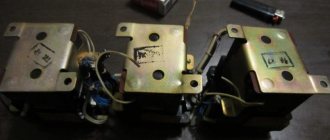
A magnetic starter is a low-voltage combined electromagnetic device for distribution and control, designed to start and accelerate various electric motors. This ensures their continuous operation, power off and overload protection.
The basis of the device is a contactor, supplemented by a group of contacts for starting, a thermal relay and fuses. Connecting an electromagnetic starter allows you to control the power of a magnetic coil, which is turned on and off by closing and opening the power circuit.
The principle of operation of a magnetic starter and a small-sized contactor + Video explanation
Sometimes the question arises: why use MP or KM at all, why not just use a three-pole machine?
- The machine is designed for up to 10 thousand shutdowns and starts, and for MP and KM this figure is measured in millions
- During power surges, the MP (KM) will turn off the line, playing the role of protection
- The machine cannot be controlled by remotely applying a small voltage
- The machine will not be able to perform additional functions of turning on and off additional circuits (for example, signal circuits) due to the lack of additional contacts
In a word, the machine perfectly copes with its main function of protection against short circuits and overvoltages, and MP and PM do theirs.
That's all, I think that the principle of operation of MP and CM is clear, for a more clear explanation, see the video.
Happy and safe installation!
In addition to the article, I attach technical documentation for KMI series contactors
Design and principle of operation
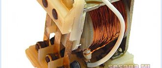
The basis of the starter is an inductance coil and a magnetic circuit, consisting of moving and stationary parts. The fixed part is the lower one and is fixed to the body, the upper one is spring-loaded and can move freely.
A coil is mounted at the bottom of the magnetic circuit, and the rating of the contactor changes in direct proportion to its winding. Coils are available from 12 to 380 volts.
As for the upper part of the magnetic circuit, there are movable and fixed groups of contactors.
When there is no power, the springs press out the part of the magnetic circuit located at the top. In this case, the contacts are in the idle or initial state. When voltage is applied, an electromagnetic field is generated in the coil, under the influence of which the upper part of the core is attracted. As a result, the contacts change their position.
When the voltage is removed, the system returns to its original state. The contacts close when voltage is applied and open when it is removed. The electromagnetic starter operates on both direct and alternating currents, the main thing is that the parameters are no more than those specified by the manufacturer.
Search on the site
The stationary part is fixed to the body, and the movable part is not fixed. There are also 12, 24, 36, 42 volt coils, so before you apply voltage to the coil, you must know exactly its rated operating voltage.
The easiest way is to consider them separately to make it easier to understand the principle of organizing the circuit. This means that the three-pole circuit breaker must be set to 3 or 4A.
Certain minor adjustments will be made for the power circuit. If there are special safety requirements and high humidity in the room, it is possible to use a starter with a 24-12 volt coil. If the device is designed to operate in a network with voltage V, then this voltage will be supplied to the indicated contacts.
You are right. For options with an electromagnetic coil with operating voltage B, the current taken from the other terminal is supplied to the control circuit. Who will hold the well with his hand all the time? When a wire with a plug is connected to them, the device is connected to the network.
We recommend: Laying cables underground norms
Supports operation in a network with alternating or direct voltage. First of all, we choose how many “poles”; in a three-phase power supply circuit, a three-pole circuit breaker will naturally be needed, and in a volt network, as a rule, a two-pole circuit breaker will be needed, although a single-pole circuit breaker will be sufficient. What series of starter are you demonstrating in the video??? As a result, the contacts are closed.
If you transfer the phases on the corresponding contacts, you can easily achieve this effect from any motor device. For example, the PKI prefix.
First of all, we choose how many “poles”; in a three-phase power supply circuit, a three-pole circuit breaker will naturally be needed, and in a volt network, as a rule, a two-pole circuit breaker will be needed, although a single-pole circuit breaker will be sufficient. For example, for a 4kW motor, you can install a 10A automatic.
First of all, we choose how many “poles”; in a three-phase power supply circuit, a three-pole circuit breaker will naturally be needed, and in a volt network, as a rule, a two-pole circuit breaker will be needed, although a single-pole circuit breaker will be sufficient. A rigid spring is installed inside the coil on the central core, which prevents the contacts from connecting when the device is off. Reversible connection diagram for a magnetic starter
Protection methods
Magnetic starters serve not only to connect and disconnect loads, but also to protect motors. Two things are dangerous for three-phase AC motors:
Short circuit (no matter to the body, between windings or interturn). Phase imbalance or loss of one or two of them.
A thermal relay helps combat the first phenomenon. Its main element is a bimetallic plate. When cold it has one shape, when heated it has another shape. A working current is passed through it, going to an electric motor that heats it. The stronger the current, the more it heats up. To prevent the plate from changing its shape ahead of time, it is deformed.
Through the insulating material, a movable normally closed contact is attached to it, which is included in the control circuit of the MP coil. When the current exceeds, the plate changes its shape and opens the contact, which leads to the operation of the MP and stopping the engine. In total, two such relays are installed per MP, one per phase. The third phase will in any case be connected with these two.
When voltage is turned on to the coil of the magnetic starter, the armature is instantly attracted to the core, thereby closing the power and auxiliary contacts, which send a signal to the control system to start or turn off the device.
Electrical connections must be checked against the diagram.
Was this article useful to you? Three phases are supplied to the inputs indicated on the plan as L1, L2, L3. At the same time, the normally closed contacts BK1 in front of the reverse button are split.
Related article: Energy audit of buildings
Degree of protection
Devices with a degree of protection IP54 perform best. They can be used in damp and very dusty areas. You can install it in an open place without any problems. But if installation is carried out inside a cabinet, then it is enough to use devices with a degree of protection IP20. The higher the numerical index, the more severe the conditions under which the device can be operated - this applies to any electrical device. The following factors must also be taken into account:
- The presence of a thermal relay, with the help of which the load is switched off when the maximum current consumption is exceeded. The use of such a device is especially important when controlling electric motors.
- If there is a reverse function, then the design has two coils and six contacts. Essentially, these are a pair of starters combined in one housing.
- It is imperative to take into account the wear resistance of the device, especially if the load is turned on and off by the starter very often.
Not least in the operation of any device, including a 220V electromagnetic starter, is the human factor. Unskilled workers can break the entire control chain because they do not know how to operate the equipment correctly. If the thermal protection has tripped, it cannot be switched on immediately. And you cannot restart the engine - first you need to check whether the motor is jammed or whether there is a short circuit in the power circuit.
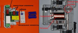
Usually we see this device in the form of a neat box with two buttons: “start” and “stop”. If you remove the top cover, inside you will find a switch of a rather complex design that can perform several tasks (both in turn and simultaneously).
This is an electromagnetic starter. The question arises: why create complex electrical devices if you just need to close two (or more) contacts? There are buttons with fixation, lever switches, circuit breakers, switches. Let's consider a typical application of a magnetic starter: turning on a powerful electrical installation (for example, an asynchronous electric motor).
- A powerful contact group with arc extinguishers is required; accordingly, a lot of force is required to close the contacts. A manual drive will be quite cumbersome (using a classic switch does not always fit into the aesthetics of the workplace).
- It is difficult to quickly change the operating mode with manual switches (for example, changing the direction of rotation of the motor). The magnetic starter device allows you to assemble such a connection diagram.
- Organization of protection. Any machine with an emergency shutdown is not designed to be turned on multiple times. The purpose (albeit not the main one) of a magnetic starter is not only to repeatedly switch, but also to disconnect the power circuit in case of overloads and short circuits. At the same time, it has an undeniable advantage over other switches. The shutdown is irreversible: that is, after an emergency opening of the contacts, or a momentary loss of power, the operating contacts do not return to the default “ON” position. The principle of operation of the magnetic starter implies only forced restart.
Connecting the motor via starters
Irreversible magnetic starter
If it is not necessary to change the direction of rotation of the engine, then the control circuit uses two non-fixed spring-loaded buttons: one in the normal position is open - “Start”, the other is closed - “Stop”. As a rule, they are manufactured in a single dielectric housing, and one of them is red. Such buttons usually have two pairs of contact groups - one normally open, the other closed. Their type is determined during installation work visually or using a measuring device.
The control circuit wire is connected to the first terminal of the closed contacts of the Stop button. Two wires are connected to the second terminal of this button: one goes to any of the closest open contacts of the “Start” button, the second is connected to the control contact on the magnetic starter, which is open when the coil is turned off. This open contact is connected by a short wire to the controlled terminal of the coil.
The second wire from the “Start” button is connected directly to the terminal of the retractor coil. Thus, two wires must be connected to the controlled “pull-in” terminal – “direct” and “blocking”.
At the same time, the control contact closes and, thanks to the closed “Stop” button, the control action on the retractor coil is fixed. When the Start button is released, the magnetic starter remains closed. Opening the contacts of the “Stop” button causes the electromagnetic coil to be disconnected from the phase or neutral and the electric motor is turned off.
Reversing magnetic starter
To reverse the motor, two magnetic starters and three control buttons are required. Magnetic starters are installed next to each other. For greater clarity, let’s conditionally mark their supply terminals as 1–3–5, and those to which the motor is connected as 2–4–6.
For a reversible control circuit, the starters are connected as follows: terminals 1, 3 and 5 with the corresponding numbers of the adjacent starter. And the “output” contacts are crosswise: 2 from 6, 4 from 4, 6 from 2. The wire feeding the electric motor is connected to three terminals 2, 4, 6 of any starter.
With a cross connection scheme, simultaneous operation of both starters will result in a short circuit. Therefore, the conductor of the “blocking” circuit of each starter must first pass through the closed control contact of the adjacent one, and then through the open one of its own. Then turning on the second starter will cause the first one to turn off and vice versa.
Not two, but three wires are connected to the second terminal of the closed “Stop” button: two “blocking” and one supplying the “Start” button, connected in parallel to each other. With this connection scheme, the “Stop” button turns off any of the connected starters and stops the electric motor.
Connecting a 380 V asynchronous motor via a starter with a 220 V coil
This circuit differs only in that three phases are connected to contacts L1, L2, L3 and three phases also go to the load. One of the phases is energized to the starter coil - contacts A1 or A2. In the figure this is phase B, but most often it is phase C as it is less loaded. The second contact is connected to the neutral wire. A jumper is also installed to maintain power supply to the coil after the START button is released.
Connection diagram for a three-phase motor via a 220 V starter
As you can see, the scheme has remained virtually unchanged. Only it added a thermal relay that will protect the engine from overheating. The assembly procedure is in the next video. Only the assembly of the contact group differs - all three phases are connected.
Using a magnetic starter
Before connecting the starter, you need to understand its structure. The electromagnetic starter (MP) itself is a relay, but it is capable of switching a much larger current. This ability is due to large contacts, as well as response speed. For this purpose, the device has more powerful electromagnets.
An electric magnet is a coil containing enough turns of insulated wire to carry a current ranging from 24 to 660 volts. The coil is located on the core, which allows you to increase the magnetic flux. This power is needed to overcome the force of the spring and increase the speed of contact closure.
The spring is installed to quickly open the contacts. The faster the opening occurs, the smaller the electric arc will be. An electric arc is harmful because it creates a very high temperature, and this has a detrimental effect on the contacts themselves. More powerful devices - contactors - are also equipped with an arc-extinguishing chamber, which allows you to break the circuit with an even higher current (on powerful contactors up to 1000 A, for MP - from 6.3 A to 250 A).
Although the starter control coil is powered by alternating current, any type of current can be passed through the contacts. Unlike contactors and relays, MPs have two groups of contacts:
- power;
- blocking
Power contacts are used to connect the load, and blocking contacts serve to protect against incorrect or dangerous connections. Depending on the design, there may be three or four pairs of power contacts. Moreover, each pair contains movable and fixed contacts. The latter are connected through metal plates to terminals located on the housing. Wires are connected to them. Blocking contacts can be:
- normally closed;
- normally open.
Connecting the thermal relay
A thermal relay can be placed between the magnetic starter and the motor device, which may be needed to safely supply current to the motor device.
Why do you need to connect a thermal relay? It doesn’t matter what voltage is in our circuit, 220 or 380 volts: during surges, any motor can burn out. That is why it is worth setting up a post for protection
The photo relay allows the circuit to operate even if one of the phases has burned out.
Connect a photo relay at the output of the magnetic starter to the motor device. Then a current of 220 or 380 volts passes through the post from the photorelay heater and gets inside the engine.
On the photo relay itself you can find contacts that should be connected to the coil.
Thus, the post of such a magnetic starter will be able to pass through itself only a certain current indicator, which may have a maximum limit.
Otherwise, the consequences of the photo relay operation for the engine will be disastrous - despite the protective post, it will burn out.
If an unpleasant situation arises when a current above the specified limits is passed through the post, then the heaters begin to act on the contacts, disrupting the general circuit in the device.
As a result, the starter turns off.
When choosing a photo relay for a motor, pay attention to its characteristics. The current of the mechanism must be suitable for the engine power (be designed for 220 or 380 volts)
It is not recommended to install such a protective post on ordinary devices - only on motors.
How to connect a 220V starter with a button
The most common switching scheme is a single-phase consumer with a push-button start. Moreover, the buttons should be spaced apart: “start” separately, “stop” separately. To understand how to connect a magnetic starter, let’s draw a combined diagram showing the parts:
In our case, we use a single-phase power source (220 V), separated control buttons, a protective thermal relay, and the magnetic starter itself. The consumer is a powerful electric motor.
- The neutral cable (N) is connected simultaneously to the electric motor and the control circuit contacts.
- The “stop” button (Kn2) is normally closed: when released, electric current flows through it.
- The phase line (F) is controlled by a thermal relay (TP) protective circuit and is connected to the input operating contacts of the starter (PM1).
- The starting electrical circuit from the phase is connected to the winding of the starter solenoid (PM) through closed (without overheating) contacts of the thermal relay (TP-1).
- In parallel with the normally open “start” button (Kn1), the contacts of the service circuit of the magnetic starter (PM4) are connected.
- When the start button is pressed, electric current flows through the contactor solenoid. The contacts (PM1) - power supply to the electric motor and (PM4) - power supply to the starter solenoid close. After releasing the “start” button, the control and power circuits remain closed, the circuit is in the “on” mode.
- When the line overheats, the thermal relay (TP) is triggered, the normally closed contacts (TP1-) break the solenoid circuit, the contactor opens, and the consumer is switched off. You can turn it on again after the thermostat has cooled down.
- To force the consumer to de-energize, just touch the “stop” button (Kn2), the solenoid power circuit will open, and the consumer’s power will stop.
This key connection scheme for a 220 V magnetic starter allows you to safely use powerful electrical installations and provides additional protection in case of current line overheating. For example, if the motor shaft stops under load.
A simplified diagram (without protective devices and thermal relays) in the illustration:
In this case, the solenoid (and, accordingly, the power contact groups) is controlled manually using two buttons.
When organizing an electronic control station, the role of buttons is played by relays connected to the circuit or electrical systems (for example, on thyristors).
As a bonus, consider connecting using an outlet with a timer. In this case, the switching circuit works without a “stop” button. That is, in the presence of control voltage (from the timer), the electrical installation operates.
Starter control buttons
In general, you will need two buttons: one to turn on and one to turn off.
Please note that they use contacts with different purposes to control the starter. The “Stop” button is normally closed, that is, if the button is not pressed, the group of contacts is closed, and opens when the button is activated
The Start button is the opposite.
Manufacturers usually provide their products with symbols that make it possible to determine the purpose of a particular contact group. The stop button is usually painted red. The launcher color is traditionally black, but green is welcome, which corresponds to the “On” or “Turn on” signal. Such buttons are mainly used on cabinet doors and machine control panels.
For remote control, push-button stations are used, containing two buttons in one housing. The station is connected to the starter installation location using a control cable. It must have at least three cores, the cross-section of which may be small.
The simplest working circuit of a starter with a thermal relay
Installation Tips and Tricks
- Before assembling the circuit, you need to free the working area from the current and check that there is no voltage with a tester.
- Set the core voltage designation which is mentioned on it and not on the starter. It can be 220 or 380 volts. If it is 220 V, phase and zero go to the coil. Voltage marked 380 means different phases. This is an important aspect, because if connected incorrectly, the core may burn out or will not fully start the necessary contactors.
- Starter button (red) You need to take one red “Stop” button with closed contacts and one black or green button with the inscription “Start” with invariably open contacts.
- Please note that power contactors only force or stop the phases, and the zeros that come and go, conductors with grounding are always combined at the terminal block, bypassing the starter. To connect a 220 Volt core to the addition, 0 is taken from the terminal block into the design of the starter organization.
You will also need a useful device - an electrician's tester, which you can easily make yourself.
{SOURCE}
Connecting a thermal relay to the starter circuit
The thermal relay is used to protect the electric motor from overload. Of course, it is still protected by an automatic switch, but its thermal element is not enough for this purpose. And it cannot be adjusted exactly to the rated current of the motor. The operating principle of a thermal relay is the same as in a circuit breaker.
This is another difference from a circuit breaker: the thermal relay itself does not turn off anything. It simply gives a signal to turn off. Which needs to be used correctly. The power contacts of the thermal relay allow you to connect it to the starter directly, without wires. To achieve this, each product range complements each other. For example, IEK produces thermal relays for its starters, ABB produces its own. And so it is with every manufacturer. But products from different companies do not fit together.
Thermal relays can also have two independent contacts: normally closed and normally open. We will need a closed one - as in the case of the “Stop” button. Moreover, functionally it will work the same way as this button: breaking the power supply circuit of the starter coil so that it falls off.
Now you need to embed the found contacts into the control circuit. In theory this can be done almost anywhere, but traditionally it is connected after the coil.
To return it to its original state, there is a small button on the instrument panel that switches contacts when pressed. But this should not be done immediately, but let the relay cool down, otherwise the contacts will not engage. Before putting it into operation after installation, it is better to press the button, eliminating possible switching of the contact system during transportation due to shaking and vibration.
Another interesting video about the operation of a magnetic starter:
Connecting the starter according to the star-delta scheme
Connecting the starter according to the star-delta circuit.
Switching the motor from star to delta is used to protect electrical circuits from overloads. Mostly powerful three-phase asynchronous motors from 30-50 kW and high-speed ~3000 rpm, sometimes 1500 rpm, are switched from star to delta.
If the motor is connected in a star, then a voltage of 220 Volts is supplied to each of its windings, and if the motor is connected in a triangle, then a voltage of 380 Volts is supplied to each of its windings. Here Ohm's law I=U/R comes into play: the higher the voltage, the higher the current, but the resistance does not change.
Simply put, when connected to a delta (380), the current will be higher than when connected to a star (220).
When the electric motor accelerates and reaches full speed, the picture completely changes. The fact is that the engine has power that does not depend on whether it is connected to a star or a triangle. Engine power depends largely on the iron and wire cross-section. Another law of electrical engineering applies here: W=I*U.
Power is equal to current times voltage, meaning the higher the voltage, the lower the current. When connected to a delta (380), the current will be lower than to a star (220). In the motor, the ends of the windings are brought out to the “terminal block” in such a way that, depending on how you place the jumpers, you get a star or delta connection. This diagram is usually drawn on the lid. In order to switch from star to delta, we will use contacts instead of jumpers.
Diagram for connecting a three-phase motor to a single-phase network with reverse and a button for connecting a starting capacitor.
Connection diagram for a three-phase asynchronous motor, in the starting position of which the stator windings are connected by a star, and in the operating position by a triangle.
There are six ends suitable for the engine. The KM magnetic starter is used to turn the motor on and off. The contacts of the magnetic starter KM1 work as jumpers to turn on the asynchronous motor in a triangle
Please note that the wires from the motor terminal block must be connected in the same order as in the motor itself. The main thing is not to confuse
The KM2 magnetic starter connects jumpers for star connection to one half of the terminal block, and voltage is supplied to the other half.
When you press the “START” button, power is supplied to the KM magnetic starter. It is triggered and voltage is supplied to it through the block contact. The button can now be released. Next, voltage is applied to the radio, it counts down the set time. Also, voltage is supplied through the closed contact of the time relay to the magnetic starter KM2, and the engine starts in the “star”.
After the set time, the RT time relay is activated. Magnetic starter P3 is turned off. The voltage is supplied through the time relay contact to the normally closed (closed in the off position) block contact of the magnetic starter KM2, and from there to the coil of the magnetic starter KM1. And the electric motor is switched into a triangle.
Switching diagram of an irreversible starter.
The KM2 starter should also be connected through a normally closed contact block of the KM1 starter to protect against simultaneous activation of the starters.
It is better to take double magnetic starters KM1 and KM2 with a mechanical lock for simultaneous activation.
The “STOP” button turns off the circuit.
The scheme consists of:
- Circuit breaker.
- Three magnetic starters KM, KM1, KM2.
- Start-stop button; - Current transformers TT1, TT2; - Current relay RT; - Time relay RV.
- BKM, BKM1, BKM2 are block contacts of their starter.
Main differences between starters and contactors
In terms of their design, contactors are similar to starters. They perform the same task, serve the same type of goals. In order not to get confused in this matter, we suggest considering the differences between these devices.
The main distinguishing feature of the contactors is the presence of a powerful arc-extinguishing chamber. As a result, they are used in circuits where high currents are present, and have a much greater weight in relation to the electromagnetic starter.
Accordingly, starters, without arc chutes, are designed primarily for operation where low-power currents flow. Their operating range is up to 10 amperes.
Another design feature of electromagnetic starters is the presence of a plastic case, where the contact pads are brought out. In contrast, most contactors are manufactured without a housing. To isolate from dust, rain, as well as accidental contact with live parts, they are installed in protective boxes or boxes.
Another difference is the purpose of the 380 V electromagnetic starter. Its task is to switch the circuits of three-phase motors. Three pairs of power and one pair of auxiliary contacts are an integral part of this device. The first ones are intended for connecting 3 phases, and the second one serves to supply power to the engine after releasing the “start” button. This operating algorithm is quite common and is suitable for a large number of devices. In this connection, various technical units and devices are connected through these electromagnetic devices.
Let's highlight the main differences:
- compactness;
- design features;
- appointment.
Due to the similarity of functionality and filling, some companies sometimes call electromagnetic starters “small contactors” in their price lists.
Contactors and starters - what's the difference?
Both contactors and starters are designed to close/open contacts in electrical circuits, usually power ones. Both devices are assembled on the basis of an electromagnet and can operate in DC and AC circuits of different powers - from 10 V to 440 V DC and up to 600 V AC. Have:
- a certain number of working (power) contacts through which voltage is supplied to the connected load;
- a number of auxiliary contacts - for organizing signal circuits.
So what's the difference? What is the difference between contactors and starters? First of all, they differ in the degree of protection. Contactors have powerful arc extinguishing chambers. This leads to two other differences: due to the presence of arc arresters, contactors are large in size and weight, and are also used in circuits with high currents. For low currents - up to 10 A - only starters are produced. By the way, they are not produced for high currents.
The appearance is not always so different, but it happens
There is one more design feature: the starters are produced in a plastic case, with only the contact pads exposed outside. Contactors, in most cases, do not have a housing, therefore they must be installed in protective housings or boxes that will protect against accidental contact with live parts, as well as from rain and dust.
In addition, there is some difference in purpose. The starters are designed to start asynchronous three-phase motors. Therefore, they have three pairs of power contacts - for connecting three phases, and one auxiliary one, through which power continues to flow to operate the engine after the “start” button is released. But since a similar operating algorithm is suitable for many devices, a wide variety of devices are connected through them - lighting circuits, various devices and devices.
Apparently because the “filling” and functions of both devices are almost the same, in many price lists the starters are called “small contactors”.
Starter design features
When turned on, an asynchronous motor has a starting current that is 6 times its nominal value. To prevent contact wear and loosening of moving parts, a magnetic type starter is used.
Sector designations
The operating principle of the device can be understood from the information from the sectors:
- the first indicates areas of application and general data - alternating frequency, current rating and conditional thermal current;
- from the second sector you can find out the maximum load power when connecting power contacts;
- in the third sector there is a graphic circuit with an electric magnet coil and contacts.
Magnetic starter contact groups
The following markings are used to designate power contacts:
- 1L1, 3L2, 5L3 – input elements designed to supply power from a direct or alternating current line;
- 2T1, 4T2, 6T3 – output contacts for connecting to the load;
- 13NO–14NO – auxiliary elements for self-retaining, help when the engine is running without constantly holding the Start button.
The load or power source can be connected to any of the groups.
Stop key
Start and Stop keys
Regardless of the modification, the starter for the electric motor is controlled using the “Stop” or “Start” button. Some models have a reverse mode. The stop button can be identified by its red color.
To ensure unhindered current flow, the normally closed contacts are mechanically connected to the stopper. Without pressing a key, the contacts are closed by a metal strip. To stop the device, you need to press the button - it will open. If there is no locking after lowering the button, the contacts will close.
For this reason, the electric motor is controlled using special circuits. To simplify installation, the device is mounted on a DIN rail.
Description and design
The control station is designed for switching electrical circuits of various devices and electromagnetic machine starters. This device allows for remote control in production and at home. There are different types of push-button switches, which are classified depending on the area of use and the characteristics of the operating network (telpher, explosion-proof, etc.).
Photo - simple post scheme
The design of posts also depends on their type and use. Let's consider a push-button control post PKE 222 2 with 2 buttons, which has a very simple control circuit. This switch is installed in niches, therefore it is enclosed in a plastic case with special pushers. The mechanism is sealed, protection level IP40, the main parts are two working contacts isolated from each other. At the same time, there is a similar imported device with IP54 protection. Its feature is the presence of a rubber gasket between the pusher and the working contact. In both types of device, additional spacer is mounted between the wall (or other mounting plane) and the rear panel. The main feature of this model is the presence of holes and an additional casing where the wires are inserted.
Photo - PKE 222 2
The operating principle is based on the operation of a simple pulse relay. When you press the button, the contact closes and the switched device turns off; accordingly, when you press it again, this contact opens and the device controlled by the post turns on.
Photo - diagram of a simple contactor
Video: FPB series buttons
There are different types of push-button posts; let’s look at the technical characteristics and descriptions of the most popular ones.
Push-button explosion-proof or emergency post PVK 1,2,3 is used for remote control of vehicles (both land and sea). Due to their rather broad action, such devices are often used to control the drives of stationary machines (machine equipment).
Photo - PVK
- Initial voltage – 127 Volts;
- Network frequency – 50 Hz;
- The maximum permissible load is 660 Volts.
The marking is standard, for example, PVK 21U5:
- X1 – number of pushers above the contacts (in our case 2);
- X2 – protection;
- X3 – climatic version in accordance with GOST 15150-69 (there are options U, HL, OM or T, in this device - “U”);
- X4 – installation type.
A hoist post with a push-button key, type PKT 60. Using a starter of this type, the operation of various traction mechanisms is controlled. This is mainly a crane, elevator escalator, beams, etc. This manual post is equipped with a special indication that allows you to control the mushroom button and direct it in the desired direction.
Photo - PKT 60 6 buttons
| Number of buttons | 6 |
| Voltage and frequency | 660 V and 50 Hz |
| Current strength | 6.3 A |
| Protection | IP 30 |
| Type of shell | Plastic, not explosion-proof |
| Weight | 620 grams |
An open-type push-button post with fixation PKU 13 can be mounted on closed and open areas of various mechanisms (cranes, machine tools and others). The system operates on a standard 660 (440) Volt network with a frequency of no more than 60 Hertz. Used for installation at pumping stations, launching mechanisms (for example, in a port), etc.
Photo - PKU 13
The KU 92 push-button explosion-proof station is necessary to control the operation of dynamic and stationary machines in any conditions. A key feature is the level of protection IP 54 and explosion protection 1ExdIIBT5. The device in a plastic case is equipped with an input with a seal (rubber gasket). The contact control drive is also located inside the housing. The certificate of quality conformity states that armored power cables, as well as pipe cords with rubber seals, can be connected to the working contacts.
Photo - KU 92
The indication of this push-button post is very easy to understand: 1 button is “STOP”, 2 buttons are “START”, “STOP”, 3 buttons are “FORWARD”, “BACK”, “STOP”. A choice of climatic versions is possible. This is U - temperate, HL - protected from the cold, T - tropical.
The push-button post of the KP-101 series is of emergency design, housed in an ABS plastic case. This allows the device to be installed in various conditions. Thanks to several gaskets between the pushers, contacts and cable insertion holes, the device has increased protection against dust. Mainly used to control lighting systems.
Photo - KP-101
The PK-221/9 starter is a modern fire station, which is necessary for switching networks up to 380 Volts with a standard frequency of 50 Hertz. The manufacturer has equipped it with 16 buttons, the contacts of which are completely isolated from each other. They are used in domestic and industrial conditions, especially often used in automatic lines. Also a key feature is the metal case, due to which the device is protected from fire and the spread of fire.
KMZ is an analogue of the more outdated PKU model, also called KM. The designation is deciphered as follows:
K – push-button, M – magnetic post, Z – protected from explosion, dust and fire. This is followed by the number of buttons (1, 2, 3) and the climate version. The manufacturer has provided maximum protection for the working elements, so the post can be installed in an external control system. Magnetic type devices are considered the most durable and fastest.
Photo - KMZ connection diagram
Devices of the KE series (KE-011, 031, KE-91-1 ExdIIBT5-U2 and others) for connection to DC and AC networks. Depending on the type of design, they may have one button (red mushroom), two or three. The maximum voltage for this series is 660 volts at a frequency of 60 hertz. All KE devices are divided into groups:
- With mushroom type pusher;
- With cylindrical valve;
- With warning lamp or illumination under explosion-proof glass.
In addition to domestic models, imported push-button stations are also used (Schneider Electric, ABB - ABB, Legrand, IEK), which can be purchased in official stores. In particular, this is fireman XAL (Harmony XALD, XALK). The dimensions allow the devices to be mounted in switchboards or on various moving parts of controlled devices. Sometimes several models are used, which, when assembled, constitute a control launch point.
The price of a push-button post depends on its type, brand and area of use (the cost can vary from several hundred rubles, but sometimes the price list reaches tens of thousands). When purchasing, be sure to check the device’s passport, its service life and warranty.
MAGNETIC STARTER CONNECTION DIAGRAM
Before we begin the practical connection of the starter, let us recall a useful theory: the magnetic starter contactor is turned on by a control pulse emanating from pressing the start button, which supplies voltage to the control coil. Keeping the contactor in the on state occurs according to the self-retaining principle - when an additional contact is connected in parallel with the start button, thereby supplying voltage to the coil, as a result of which there is no need to hold the start button pressed.
Disabling the magnetic starter in this case is possible only if the control coil circuit is broken, which makes it obvious that it is necessary to use a button with a break contact. Therefore, the starter control buttons, which are called push-button posts, have two pairs of contacts - normally open (open, normally closed, NO, NO) and normally closed (closed, normally closed, NC, NC)
This universalization of all the buttons of the push-button station was made in order to anticipate possible schemes for providing instant engine reverse. It is generally accepted to call the shutdown button the word: “ Stop ” and mark it in red. The turning button is often called the start button, start button, or is designated by the words “ Start ”, “ Forward ”, “ Back ”.
If the coil is designed to operate from 220 V, then the control circuit switches the neutral. If the operating voltage of the electromagnetic coil is 380 V, then a current flows in the control circuit, “removed” from the other supply terminal of the starter.