Voltage drops, network interference, changes in the frequency of alternating current - these factors complicate the operation of electrical networks and consumers connected to them, as they can lead to their failure. Equipment powered by three-phase lines needs protection. For this purpose, devices have been created that monitor changes in the network and ensure that electrical appliances are turned off when its parameters go beyond acceptable limits. UZM-3-63 belongs to such protective equipment and has technical characteristics that distinguish it favorably among analogues.
Purpose and scope of application of the product
UZM-3-63 provides frequency control of a three-phase power supply network, protects equipment from an increase or decrease in incoming voltage, pulsed network interference, violation of the phase sequence or the disappearance (break) of one of them. Each of the listed violations can lead to failure of electrical appliances or significantly affect the quality of their operation. The protection device can neutralize the negative effect or perform a protective shutdown.
For example, pulsed voltage surges that occur when turning on/off powerful consumers (electric motors, welding machines, etc.) have a detrimental effect on the electronics of other equipment connected to the same network. Similar interference can occur during surges at transformer substations. All phases of UZM-3-63 have semiconductor varistor protection, which can preserve the consumer and its operability during pulse overvoltages with a current amplitude of up to 6.5 kA.
The maximum current value in each phase, at which the relay’s ability to switch contacts is maintained, is 63A, which is a high indicator and allows the device to be used without using a magnetic starter in the circuit. UZM-3-63 can be used both at production facilities and in administrative buildings or households to connect three-phase current consumers.
The device does not protect against the destructive effects of short circuits, and also does not respond to current leaks, therefore the use of protective equipment such as AV and RCD in the electrical circuit is mandatory.
Main characteristics of UZM
| UZM 16 | UZM 50 M | UZM 51 M | UZM 50 MD | UZM 51 MD | UZM 50TS | |
| Voltage limitation level at interference current 100A, no more | — | 1.2 kV | 1.2 kV | 1.2 kV | 1.2 kV | 1.2 kV |
| Maximum absorption energy by built-in varistor (single pulse 10/1000µs) | 42 J | 200 J | 200 J | 200 J | 200 J | 200 J |
| Maximum absorption current, single pulse 8/20µs / repeated pulses 8/20µs | 1200 A | 6000/6000 A | 6000/6000 A | 8000/6000 A | 8000/6000 A | 6000/6000 A |
| Threshold for switching off the load when the voltage increases, Utop | 240-290 V | 265 V | 240-290 V | 265 V | 240-290 V | 240…295 V |
| Threshold for switching off the load when the voltage drops, Ulow | 210-120 V | 170 V | 210-100 V | 165 V | 210-100 V | 190-100 V |
| The upper threshold for accelerated load shedding when the voltage rises above the upper critical threshold, Uup.cr. | 300 ± 15 V | 300 ± 15 V | 300 ± 15 V | 300 ± 15 V | 300 ± 15 V | 300 ± 15 V |
| Threshold for accelerated load shedding when voltage drops below the lower critical threshold, Ulow.cr | 100±10V | 130 ± 10 V | 80±10V | 80±10V | 80±10V | 80 V |
| Overload current/exposure time without contact welding | 2000 A / 10ms | 2000 A / 10ms | 2000 A / 10ms | 2000 A / 10ms | ||
| Short circuit current without destruction | 3000 A | 3000 A | 3000 A | 3000 A |
Parameters of a universal network protection device against overvoltage and surge currents
Models UZM 50 M and 51 M differ in that conductors of larger diameters (up to 35 mm²) can be connected to them. Accordingly, they have a higher rated load current - up to 63 A. Modifications with the letter “D” - 50 MD and 51 MD - differ in that they have built-in spark protection. And the UZM 51 series is distinguished by the fact that it has manual adjustment of the voltage shutdown parameters. Using the manual regulator located on the front panel, the shutdown limits for high or low voltage are changed.
UZM-50TS and UZM-50MC (fire) are equipped with a digital indicator, which by default shows voltage and switches to measuring current and power. Of course, you can use the UZM-51MD, and install a separate VAR-M01-08 AC20-450V UHL4 voltammeter on a DIN rail in the electrical cabinet. But, if you need to save space, it is better to use UZM-50MC. There are other differences - you can select the response delay in a wide range from 10 sec to 360 sec, built-in non-volatile memory, where the number of shutdowns, minimum and maximum voltage values are stored . And, as in other 50 series models, adjustable shutdown thresholds for overvoltage and undervoltage.
Design features
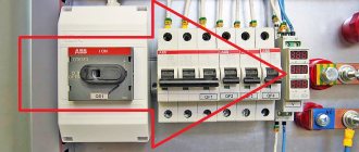
Externally, the product is a single housing with four input (N, L1, L2, L3) and output terminals (N, U, V, W). On the front panel there are regulators for setting the triggering voltage (U max, U min) and the switching time after triggering. They have a setting scale on which the user can select the values of interest. LED indicators are also located here: green - indicate the presence of phases L1, L2, L3; red – about overvoltage (U>) or undervoltage (U<); yellow ( ) – about the operation of the power relay.
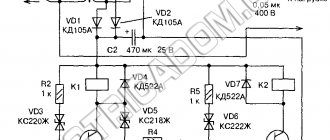
The following elements are located inside the case:
- The basis of the protective device is a powerful three-phase polarized relay, which allows the circuit to be closed/opened at high current values
- Varistors installed on each phase provide protection against pulsed network surges due to the ability to change their resistance depending on the magnitude of the incoming voltage
- Contact block driven by a power relay.
A schematic representation of these parts is shown in the figure below.
Built-in design elements of the UZM-3-63 protection device
Protection work
The lighting of the green LEDs L1, 2, 3 signals that voltage is supplied to the input terminals. If the network parameters correspond to the specified values (presence of all phases, the order of their alternation, voltage, frequency), after the set restart timer has expired, the relay closes the contacts. Electricity is supplied to the equipment, as indicated by the yellow indicator ( ).
In case of any violation, the device turns off the voltage supply. In this case, the yellow LED on the front panel stops lighting and the reason for the operation is displayed:
| Negative factor | Violation indication |
| Input voltage exceeding the specified value | "U>" lights up |
| Decreasing this parameter | “U<” lights up |
| Changing the phase order | Red LEDs flash alternately |
| The occurrence of imbalance when the voltage difference between phases is more than 25% | Red indicators blink slowly simultaneously with each other |
| Mains frequency deviation from 50 Hz | Rapid flickering of both voltage indicators (<, >) |
After the power relay is turned off, when the network parameters are restored, the restart time countdown begins, after which the device will resume supplying electricity to the load.
Protection device UZM-3-63K AC230V/AC400V UHL4
PURPOSE
The multifunctional protection device UZM-3-63 (hereinafter referred to as the device) is intended for:
- shutdown of equipment in case of violation of the phase rotation order, voltage and/or frequency in three-phase networks exceeding the standard/established parameters;
- protecting equipment (in an apartment, office, etc.) from the destructive effects of pulsed voltage surges caused by the operation of nearby motors, starters (etc.) connected to the same network, thereby preventing equipment failure and possible fire.
OPERATING PRINCIPLE OF THE DEVICE
After supplying power to the device input, the green indicators L1, L2 and L3 turn on. If the voltage is within the user-specified limits, the load is connected to the supply voltage network and the yellow indicator of the executive relay lights up.
In operating mode, the device controls the supply voltage. When high-voltage voltage pulses appear in the network, the built-in varistor shunts them to a value safe for the equipment.
Indication of device operating parameters operates in the following modes:
- if the supply voltage of one of the phases exceeds the upper shutdown threshold, the red “U>” indicator turns on and the executive relay is turned off (the yellow relay operation indicator goes out). When the mains voltage returns to the established limits, the restart delay starts counting. After the end of the time countdown (set by the user in the range from 0.1 to 10 seconds), the load is connected to the supply voltage network. If during the countdown the voltage level again goes beyond the permissible limits, the countdown of the restart time is reset;
- if the voltage of one of the phases goes beyond the lower shutdown threshold, the indicator “
- if there is a violation of the phase rotation order, the load is switched off, and the “U” indicators turn on alternately;
- if there is a change in the network frequency by more than 10%, then the load is disconnected, and the “U” indicators flicker simultaneously;
- if there is a difference in voltage level between phases in the network of more than 25%, then after disconnecting the load, the “U” indicators slowly turn on/off simultaneously.
The user can independently change the turn-on time delay (in the range from 0.1 to 10 seconds) using the adjustment knob located on the front of the device.
KEY FEATURES
- Can be used in networks of any configuration; TN-C, TN-S, TN-CS, TT;
- Network frequency control 45-50 Hz;
- Phase sequence control;
- Does not replace other protection devices (circuit breakers, SPDs, RCDs, etc.);
- Rated switching current 63A for each phase;
- Two-threshold overvoltage protection (delay): >upper threshold/(0.2s), >300V/(20ms)
- Two-threshold undervoltage protection /(delay): <lower threshold/(10s) and <130V/(100ms)
- the ability to change the restart delay time in the range from 0.1 to 10 seconds;
- Built-in varistor protection against surges in mains voltage
- Load switching time during voltage surges - 30 ms;
TERMS OF USE
The device provides guaranteed load protection subject to the following conditions:
- altitude above sea level no more than 2000m;
- the environment is explosion-proof, free of dust in quantities that would disrupt the operation of the relay, as well as aggressive gases and vapors in concentrations that destroy metals and insulation;
- The relay installation location must be protected from splashes of water, oils, and emulsions;
- vibration of the relay mounting points with a frequency from 1 to 100 Hz with an acceleration of no more than 9.8 m/s2;
- the device is resistant to interference of severity level 3 in accordance with the requirements of GOST R 51317.4.1-2000, GOST R 51317.4.4-99, GOST R 51317.4.5-99;
- Moisture condensation on the surface of the product is not allowed.
CONNECTION DIAGRAMS
ATTENTION!
When the device is triggered, only the phase wire is broken. The neutral wire N passes through for ease of installation and is not switched. It is allowed to connect terminal N only on one side (For example, when connecting three UZMs to a three-phase network, you can combine the neutral terminals on one side).
DEVICE DESIGN
The device is produced in a unified plastic case and is a voltage control relay with a powerful electromagnetic relay at the output and varistor protection. The device is installed on a 35 mm wide mounting DIN rail (GOST R IEC 60715-2003) with front connection of the power wires of the protected electrical circuits. Tunnel design terminals provide reliable fastening of wires with a total cross-section of conductors up to 35mm2. On the front panel of the device there are two indicators - a two-color (green/red) “normal-failure” and a yellow indicator for turning on the relay contact, a “TEST” button for manual control, as well as knobs for adjusting the device’s response settings.
DIMENSIONS
Additional information about the parameters and operating modes of the device can be found in the product passport (the “files” tab) .
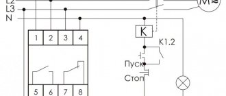
Installation and connection diagrams
The UZM-3-63 device has a mount for mounting on a 35 mm wide DIN rail. It can be installed openly in the electrical distribution panel or in a plastic case. Vertical and horizontal arrangement of the housing is allowed.
There are two connection schemes:
- When conductor N is connected to both input and output terminals of the device
- When the N wire connection is made only at the input terminal
Diagram in which conductor N is connected to the input and output of the device
Diagram in which conductor N is connected only at the input of UZM-3-63
For normal operation of the device, the zero terminal must be activated..
Purpose
The UZM-3-63 device is a voltage control relay equipped with a powerful three-phase power relay that switches a three-phase load. The relay is also equipped with a function that monitors the network frequency. In addition, there is a function for suppressing impulse noise using semiconductor varistor protection. Interference, in turn, occurs during switching of powerful devices and transients in electric motors and transformers. They have a destructive effect on microelectronics and other equipment. To switch the UMZ-3-63, no external auxiliary switching devices (starters or contactors) are required, since there is a powerful built-in 63 ampere power relay.
Main operating parameters
For ease of reference, the technical characteristics of the protective device are given in the table:
| Parameter name | Index |
| Adjustable overvoltage value for disconnecting the consumer, Volt | 243-297 |
| Adjustable voltage drop value for disconnecting the consumer, Volt | 217-163 |
| Permissible voltage difference between phases, % | less than 25 |
| Permissible fluctuations in network frequency, Hz | +5; -5 |
| max current that can be absorbed during a single mains pulse, A | 6500 |
| max current that can be absorbed during repeated network pulses, A | 4500 |
| Rated consumer power, kW | 14,5 |
| Adjustable on timer, | 2s-8min |
| Permissible cross-section of cable cores for terminals, mm² | up to 25 |
| Work mode | around the clock |
| Air humidity at temperature +25°С, % | 80 |
| Weight, kg | no more than 0.45 |
| Work resource, years | 10 |
There are operating conditions, the observance of which will ensure that the device performs its assigned functions:
- the formation of condensation on the product is unacceptable;
- preventing splashes of liquids from entering the housing;
- use at altitudes up to 2 km above sea level;
- the state of the surrounding space is non-aggressive and explosion-proof in terms of gas composition.
Storage of the product in original packaging is allowed at temperatures from -40 to +70°C for 3 years.
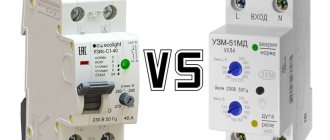
It is important to know that UZM-3-63 should not be used in the absence of three-phase equipment. In this case, it is better to install three separate devices, for example UZM-51M, which will prevent de-energization of other consumers in the absence of voltage on one of the phases .
An example of using three single-phase ultrasonic devices installed on each phase
Analogue devices from other manufacturers
Considering products from different brands designed to perform functions to protect electrical equipment from possible changes in the state of electrical networks, one can note the high quality of workmanship and versatility of these devices. They differ in name and may have differences in design, but they share a common purpose. For comparison, users are invited to familiarize themselves with some of them:
| Name | Brand | A country | The need to use switching devices (starters) | price, rub. |
| UZM-3-63 | Meander | Russia | No | 3800 |
| RNPP-302 | Novatek - Electro | Ukraine | Yes | 3000 |
| SR-731 | Euroautomation F&F | Belarus | Yes | 3660 |
| PNM-31 | ZAMEL | Poland | Yes | 3800 |
As you can see from the table, the difference in prices between products from different manufacturers is insignificant. But unlike Meander products, products from other brands require the use of additional starting devices in the circuit, because the designs of these devices provide insufficiently high switching capacity:
- the changeover relay switch in the product from Ukraine RNPP-302 is designed for a current load of 8A;
- the maximum current of the contactor coil in SR-731 from the Belarusian Manufacturing Company is 2 A;
- max load capacity of the contact of the Polish analogue PNM-31 – does not exceed 16 A.
Such values cannot provide independent switching of powerful consumers, and can only serve to control the load starter.
Analogues of protective devices for monitoring the state of a three-phase network
Another advantage of the UZM-3-63 is the possibility of remote control through terminals Y1 and Y2, located in the lower left corner of the front panel of the device.
However, some analogues also have positive design features that distinguish them favorably. For example, RNPP-302 has a digital display that visually demonstrates the state of the electrical network, which provides certain convenience during operation.
Common mistakes when installing and operating the device
- Error 1 . Installation of the product at the output of a three-phase electric meter and subsequent distribution of household voltage, converted to 220 Volts across various objects (1st phase - residential building, 2nd phase - garage, 3rd phase - outbuildings). In the event of a fault in one of the phases, the device will de-energize all branches, leaving the estate without electricity. It would be correct to install separate protection for each phase, then the shutdown will occur only in the section with the violation.
- Error 2 . Connecting a load exceeding the rated power provided by the technical characteristics of the device for each phase (more than 14.5 kW). This is unacceptable because it can lead to malfunctions of the product or its failure.
- Error 3 . Refusal to use RCDs and AVs as means of protection. The UZM-3-63 device protects equipment from network problems and works only in this direction. All violations occurring in the opposite direction, that is, emanating from the consumer, it cannot prevent or prevent. Therefore, it is better not to ignore the use of protection against short circuits and current leakage.
In conclusion, it is worth noting that the use of devices such as UZM-3-63 greatly facilitates the operation of electrical equipment, makes it safer and protected from unwanted and harmful consequences of network disturbances.
- How to connect a dimmer instead of a switch
Characteristics
The main indicators of UZM-3-63 are the following:
- Supply voltage (nominal) – 230 volts.
- Operating voltage frequency – 50 Hz.
- The maximum supply voltage is 440 V.
- The power consumed by the device is 2.2 VA.
- The rated load current is 63 A, subject to the use of copper conductors with a cross-sectional area of at least 16 mm2.
- Load power (nominal) for each phase – 14.5 kW.
- The maximum voltage for possible switching is 400 V.
- The maximum short-circuit current value for no more than 10 ms is 4500A.
The dimensions of the device – length, width and height – are 105x63x94 mm. The weight of the device does not exceed 450 grams. The work is carried out around the clock, the minimum service life is 10 years. More detailed parameters and characteristics are reflected in the technical documentation.