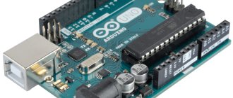
Ardublock is a graphical programming language for Arduino designed for beginners. This environment is quite easy to use, easy to install, and almost completely translated into Russian. The visually designed program, reminiscent of Scratch blocks, is easy to convert into Arduino IDE code. And you can write without looking away from the Arduino IDE - this program is built into the programming environment as a plugin. In this article we will look at issues such as Ardublock installation, configuration and programming examples.
Ardublock installation
To start working with the program, you need to install it. To do this, let's perform a few simple steps, the algorithm is as follows:
- Download the archive from the ArduBlock website
- Open Arduino IDE/Menu/Arduino/Preferences , there you will find the line Sketchbook location
- Create a folder “tools/ArduBlockTool/tool” inside the “Arduino” folder in the “Sketch location” line and copy the “ardublock-all.jar” archive into the “tool” folder. For example, if the username is “user”, then the path in the Windows environment will be: “C:\Users\user\Documents\Arduino”
- Restart the Arduino IDE and you should see the “ArduBlock” item in the “Tool” menu
When installing on a Mac for the user user, the path will be as follows: “/Users/user/Documents/Arduino/tools/ArduBlockTool/tool/ardublock-all.jar” When installing on Linux: “/home/user/sketchbook/tools/ArduBlockTool/ tool/ardublock-all.jar”
Laboratory power supply for Arduino
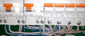
This unit is intended for a home radio amateur laboratory. Its output voltage can be adjusted from 0.5 to 15.5 V. There is protection against shorting the output or exceeding the permissible load current. Its response threshold can be changed from 0.2 to 2 A. Information about the set voltage, load current and the set current protection threshold is displayed on the LCD screen of the Nokia 5110 cell phone.
The unit is turned on and off by pressing the corresponding buttons. The third button makes it possible to temporarily turn off and turn on the voltage at the output of the unit. With its help, the unit’s functionality is restored after the current protection has tripped. When idle without load for more than 5 minutes, the unit is disconnected from the network automatically.
The power supply diagram is shown in Fig. 1. Pressing the SB3 button connects winding I of transformer T1 to the ~230 V network. The unit starts to work, and first of all, the microcontroller program sets a high logical voltage level at the output D1 of the Arduino Nano module, indicated in the diagram A1. This opens transistor VT1, relay K1 is activated and, with closed contacts K1.1, bypasses button SB3, which can now be released.
Rice. 1. Power supply diagram
On the LCD screen, the start of the unit’s operation is marked by a splash screen in the form of two rotating gears (Fig. 2), which is replaced by information about the program version (Fig. 3). Then the main image appears (Fig. 4) with the values of the output voltage, load current, power supplied to the load (the program calculates it as the product of the first two parameters) and the set protection current.
Rice. 2. Screensaver on the LCD screen
Rice. 3. Information on the LCD screen
Rice. 4. Information on the LCD screen
When you press the SB1 button, a low level at the D0 input of module A1 causes the program to display a farewell message on the screen (Fig. 5) and sets the D1 output of module A1 low. Transistor VT1 closes, relay K1 opens the contacts and thereby disconnects the unit from the network.
Rice. 5. Message on LCD screen
The output voltage stabilizer is assembled on op-amp DA1.2 and transistor VT2. The proportionality coefficient between the installed variable resistor R15, the reference voltage at the non-inverting input of the op-amp DA1.2 and the output voltage of the stabilizer is equal to R19/R18+1 (3.2 with the values of resistors R18 and R19 indicated on the diagram). These resistors form an output voltage divider, part of which is sent to analog input A6 of module A1 for measurement. The reference voltage is obtained from the reference voltage built into this ADC module, output to pin D6 of module A1, which can be turned on or off by software.
Pin D2 of module A1 is configured by the program as an input for its external interrupt requests. If the load current exceeds a specified threshold, the voltage at the inverting input of the comparator DA2 will become greater than at the non-inverting one. The output transistor of the comparator will open and shunt resistors R9 and R15 of the circuit for adjusting the output voltage of the unit, which will become zero. At the same time, a low level will be sent to the interrupt request input of program D2. The interrupt processing procedure will pause for approximately 50 ms, and then, if the overload has not stopped, it will turn off the reference voltage at output D6. As a result, the output voltage of the unit will remain zero even after the overload stops. The pause is necessary to prevent emergency protection operations when connecting to a load unit with high-capacity capacitors. The protection activation signal is the image of a palm (Fig. 6) on the LCD screen. To return the unit to operating mode, you need to press the SB2 button.
Rice. 6. Protection signal
During normal operation of the power supply, pressing the SB2 button turns off the reference voltage at output D6 of module A2, as a result of which the voltage at the output of the unit drops to almost zero. Signaling this, the image on the HG1 LCD screen will become negative. Pressing the SB2 button again will return the block to its previous state.
A variable resistor R2 motor is connected to analog input A7 of module A1, which regulates the response threshold of the unit’s current protection. By selecting resistor R1, set the minimum value of this threshold.
Pin D9 is configured by the microcontroller program as a PWM pulse output. In the Arduino Nano module, the default repetition rate of these pulses is about 490 Hz. To satisfactorily smooth out pulses traveling at such a low frequency and isolate their DC component, an overly complex filter would be required. Since there is no standard function for changing this frequency in the Arduino IDE, it was increased to 3900 Hz by directly changing a constant in the corresponding register of the microcontroller:
TCCR1B = TCCR1B & 0b11111000 I 0x02;
Rotating the knob of variable resistor R2 changes the duty cycle of the pulses at output D9. Filter R3C1 selects a constant component from the pulse sequence, which is supplied to the non-inverting input of the voltage comparator DA2 and sets its response threshold. The inverting input of the comparator receives a block voltage proportional to the load current from the current sensor (resistor R20) through an amplifier on op-amp DA1.1 with a gain of 25.
A printed circuit board for this power supply has not been developed. Everything is assembled on two breadboards measuring 50x75 mm. On one of them there is an LCD HG1 with resistors R10-R14, on the other - everything else, with the exception of transistor VT2 with a heat sink and transformer T1.
The transformer must have a power of at least 36 VA and a voltage on the secondary winding of about 18 V. The contacts of relay K1 must be designed for switching an alternating voltage of at least 250 V. If the rated operating voltage of the relay winding is less than that rectified by the diode bridge VD1, the excess must be extinguished , connecting in series with the relay winding the resistor Rext, shown in the diagram in Fig. 1 dashed line.
Attached to the article are two computer programs that facilitate the preparation of images for display on a graphic LCD. The source data for them is color or monochromatic images in *.BMP, *.JPG, *.webp, *.TGA or *.TIFF formats. The GLCD84X48 Converter program fits this image into dimensions of 84x48 pixels and converts it to a bitmap format. It produces the result as a C text file suitable for inclusion in a microcontroller program and places it under the name grap-hics.c on the computer's desktop. The OLED_LCD 128X64 I2C con-vertimage program works similarly, but generates a file for loading into a graphic display with screen dimensions of 128x64 pixels and an I2C interface.
The program for the Arduino module, libraries for it and programs for the computer are available here.
Author: O. Kolchurin, Nizhnyaya Tura, Sverdlovsk region.
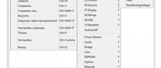
How to run ArduBlock
First, launch Arduino itself, go to the Tools menu and find ArduBlock there, select it.
First, launch Arduino itself, go to the Tools menu and find ArduBlock there, select it.
The ArduBlock window opens in addition to the Arduino window.
The ArduBlock window opens in addition to the Arduino window.
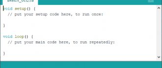
We can start programming.
Arduino language
If an experienced programmer looks at the Arduino code, he will say that it is C++ code. This is not far from the truth: the main Arduino logic is implemented in C++, and on top of it is the Wiring framework, which is responsible for communicating with the hardware.
What is the difference between C and C++
There are several reasons for this:
- C++ has a reputation for being “too complex a language.” Arduino is marketed as microcontrollers and robotics for beginners, and it is sometimes difficult to explain to beginners that C++ is not that difficult to get started with. It’s easier to make a framework and call it a separate language.
- In pure C++ there are no convenient commands for AVR controllers, so we needed a tool that would take on all the complex functions and, as a result, give the programmer frequently used commands.
- The developers allowed programmers to simply write the programs they needed, and a special development environment took over all the service commands necessary for the correct execution of code in C++.
Development environment (IDE) Arduino.
Program interface
There are no settings in ArduBlock, but there are plenty of icons for programming and each of them carries a command in Arduino IDE text format. New versions have even more icons, so understanding the latest version of ArduBlok is difficult and some of the icons are not translated into Russian.
ArduBlocks are divided into 6 categories.
Control
Control
In the "Control" section we will find a variety of loops.
Ports (Pin)
Pin
In the “Ports” section, we can manage the values of the ports, as well as the sound emitter, servo or ultrasonic proximity sensor connected to them.
Numbers, Constants and Variables
Numbers, Constants and Variables
The “Numbers/Constants” category blocks are variables
Operators
Operators
This category includes logical and mathematical operators.
Utilities
Utilities
These blocks are functions that are commonly used in sketches to control how the program works.
Modules
Bricks
Each block in this category represents a type of real device that you can connect directly to your sketch.
Scratch
This graphical programming environment was created in 2003, when a group of MIT Media Lab employees decided to develop a programming language that would be accessible to absolutely everyone. As a result, after some time, Scratch was introduced to the public.
Most of all, perhaps, it looks like Lego. At least the principle is the same: it is an object-oriented environment in which programs are assembled from parts, colorful and bright. These parts can be moved, modified, and made to interact in different ways. The basis of Scratch is blocks of commands, such as sensors, variables, movement, sound, operators, appearance, pen, control, etc. The built-in graphic editor makes it possible to draw any object. Less than five years have passed since the creation of Scratch, when the Scratch for Arduino project (abbreviated as S4A) emerged, which allows programming the Arduino PLC.
The advantages of the system include the fact that it is Russified and completely localized - anyone can find a lot of data on it. In addition, working in this graphical environment is accessible even to primary schoolchildren who are not yet very confident in reading.
Advice. There is a special resource for beginners in Scratch: https://scratch-ru.info.