No consumer electronic device lasts forever. From time to time they require timely maintenance or even repairs. All warranty service workshops are well aware that before starting repairs and inspection of the board, it is necessary to discharge the capacitor. Even after disconnecting the device from the network, they inevitably accumulate a supply of electrical energy of up to 330 Volts. Find out how to carry out this operation quickly and safely with your own hands in this material.
Discharge with a screwdriver
First we need a suitable screwdriver with an insulating handle.
As a rule, the handles are made of rubber or plastic. Both materials are capable of creating a safe barrier between the hand and the metal part of the screwdriver. If you are not sure that you have an insulating screwdriver, it is recommended to buy a new one that has a logo with the maximum permissible voltage.
Such tools are sold in the electrical goods department of any hardware department. Both a flathead and a Phillips screwdriver will do.
Now the discharge process itself.
- Grasp the element with one hand at the base, without squeezing too much;
- Place a screwdriver on both terminals;
- A discharge sound and slight sparking will be heard.
Hold the screwdriver so that it touches both legs at the same time, only then the discharge process will occur normally.
To check, you can close the terminals with a screwdriver again.
You can check the degree of discharge with the same multimeter.
It's better to check first
First, this element needs to be de-energized. It is clear that there is no need to deprive it of its power source. It is enough to turn off the electrical appliance and disconnect the plug from the socket. If you approach this issue radically, then for safety you can turn off all the circuit breakers at the switchboard that are responsible for supplying electricity to the room.
Now we need a special device - a multimeter - to find out whether the capacitor is charged.
- Select the mode for measuring DC voltage (direct current).
- We set the device knob to the maximum voltage measurement level.
- We connect the multimeter probes to the contacts of the electronic component. As a rule, two rods protrude from it. It is to them that you need to connect both probes of the detector. You need to press firmly enough so that digital readings appear on the device display. It makes no difference which probe goes to which contact. The resulting value will be the same in both cases.
We need to understand what voltage is at the terminals of the element. Depending on the indications, the discharge method is selected:
- If the reading is less than 10 volts, there is no need to discharge.
- If the display shows measurements between 10–99 volts, you can discharge it with a screwdriver.
- If values are 100 volts or higher, it is recommended to use a discharge device.
How to check a high voltage microwave capacitor
The high-voltage capacitor is checked by connecting it together with a 15 W X 220 V lamp. Next, turn off the combined capacitor and the lamp from the socket. When the part is in working condition, the lamp will glow 2 times less than usual. If there is a malfunction, the light bulb shines brightly or does not glow at all.
Checking with a light bulb
The microwave capacitor has a capacity of 1.07 mF, 2200 V, so testing it with the support of a multimeter is quite simple:
1. It is necessary to connect the multimeter so as to measure resistance, namely the highest resistance. Make up to 2000k on your device.
2. Then you need to connect the uncharged device to the terminals of the multimeter without touching them. In operating condition, the readings will become 10 kOhm, going to infinity (on monitor 1).
3. Then you need to change the terminals.
4. When, when you connect it to the device, nothing changes on the multimeter monitor, this means that the device is broken; when there is zero, it means that there is a breakdown in it. If there is a constant resistance reading in the device, even a small value, it means there is a leak in the device. It needs to be changed.
Checking with a multimeter
Checking with a multimeter
These tests are done at low voltage. Often faulty devices do not show problems at low voltage. Therefore, for testing you need to use either a megohmmeter with a voltage equal to the voltage of the capacitor, or you will need an external high voltage source.
It is simply impossible to test it with a multimeter. It will only demonstrate that there is no break and a short circuit. To do this, you need to connect it to the part in ohmmeter mode - in good condition it will demonstrate a low resistance, which will increase indefinitely over a certain number of seconds.
A faulty capacitor has an electrolyte leak. It is not difficult to make the determination of capacity with a special device. You need to connect it, set it to a higher value, and touch the terminals to the terminals. Check with regulations. When the differences are small (± 15%), the part is serviceable, but when there are none or are significantly lower than normal, it means that it has become unusable.
To test a part with an ohmmeter:
1. It is necessary to remove the outer cover and terminals.
2. Discharge it.
3. Switch the multimeter to test the resistance of 2000 kiloohms.
4. Examine the terminals for mechanical defects. Poor contact will negatively affect the quality of the measurement.
5. Connect the terminals to the ends of the device and observe the numerical measurements. When the numbers start changing like this: 1…10…102.1, it means that the part is in working condition. When the values do not change or zero appears, the device is not working.
6. For another test, the device must be discharged and confirmed again.
Discharge with a screwdriver
First we need a suitable screwdriver with an insulating handle. As a rule, the handles are made of rubber or plastic. Both materials are capable of creating a safe barrier between the hand and the metal part of the screwdriver.
If you are not sure that you have an insulating screwdriver, it is recommended to buy a new one that has a logo with the maximum permissible voltage.
Such tools are sold in the electrical goods department of any hardware department. Both a flathead and a Phillips screwdriver will do.
Now the discharge process itself.
- Grasp the element with one hand at the base, without squeezing too much;
- Place a screwdriver on both terminals;
- A discharge sound and slight sparking will be heard.
Hold the screwdriver so that it touches both legs at the same time, only then the discharge process will occur normally.
To check, you can close the terminals with a screwdriver again.
You can check the degree of discharge with the same multimeter.
Parameters and operating principle
The amount of electricity accumulated by the product, as well as the periods of discharge and charging cycles of the capacitor, are determined by characteristics that depend on the type of specific model. Due to the wide range of parameters and characteristics, these radio components can be successfully used for various purposes.
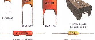
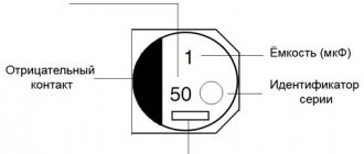
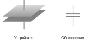
These parameters can be easily determined by the markings on the element body. Capacitors produced in Russia and the post-Soviet space are required to have alphanumeric markings indicating technology and type, TKE, rated voltage, capacitance value and production error, as well as the date of manufacture. For imported analogues, only the capacity designation is typical. In the diagrams, the capacitor is represented by two parallel lines.
Basic and additional parameters:
- Capacity (C) – the ability of a radio component to accumulate electricity (measured in farads). The capacity of the most powerful capacitors reaches several tens of farads.
- Specific capacitance - helps determine the ratio of capacitance to the mass or volume of the product (a very important parameter for microelectronics).
- Rated voltage (Uн) – allows you to determine the limit value at which the capacitor can be operated.
- Polarity is an important parameter, failure to comply with which can lead to failure of the radio element and even an explosion.
- Risk of destruction - to prevent explosion and short circuit, the device may be equipped with a safety valve or special notches on the cover.
There are also parasitic parameters that manufacturers try to reduce when manufacturing products. When choosing radio components, you should take into account stability, capacitance, leakage current, operating voltage, accuracy and temperature coefficient of capacitance.
The principle of operation is the accumulation of electrical charges due to the presence of dielectric material between metal plates on which electrons and ions are collected. Passing through this device, the current strength has the greatest value and the minimum voltage, but as electricity accumulates, the voltage increases, and the current strength, on the contrary, drops until it disappears completely. Under ideal conditions, the charging time of the capacitor is zero.
Types and applications
There are many ways to classify modern capacitors, which allow them to be grouped depending on the type of design, operating voltage, types of polarization and purpose, change in capacitance, and type of dielectric.
Types of polarization:
- ionic and ion-relaxation;
- volumetric;
- dipole-relaxation;
- electronic and electronic relaxation;
- spontaneous.
Based on the design features, there are tubular and cylindrical, monolithic, plate and sectional, disk, pot-shaped and cast, barrel, and sectional varieties.
Scope of application of capacitors:
- Electronics – radio and television equipment, storage devices, automation and various telemechanics, telegraphy and telephony.
- Electrical power engineering - discharge welding, starting electric motors, radio interference suppression, voltage regulation, electric lighting, energy extraction, use in complex circuits and generators, and voltage protection.
- Industry – mining, metallurgy and metalworking.
- Equipment – medical, laser, electrical measuring, radar, photographic, automotive.
Depending on the change in capacitance, there are constant, variable (the change is carried out mechanically or electrically) and tuning capacitors (the change is carried out one-time or periodically).
Where and why are capacitors used?
Where and why are these devices, which can operate in radio engineering, electronic and electrical devices, used? Drives are used in electrical engineering when switching on asynchronous motors for phase shifting, without which the motor as part of a single-phase circuit will not function. If the capacity is several farads, then they are used in electric vehicles to power the motor.
Application possible in various fields
Proper use of these devices will allow you to get the best results. Understanding the basic principles of physics makes operating equipment easier. Incorrect use is fraught with negative consequences caused by non-compliance with safety precautions.
What is a capacitor?
A device that stores electricity in the form of electrical charges is called a capacitor.
The amount of electricity or electric charge in physics is measured in coulombs (C). Electrical capacitance is calculated in farads (F).
A solitary conductor with an electrical capacity of 1 farad is a metal ball with a radius equal to 13 radii of the Sun. Therefore, a capacitor includes at least 2 conductors, which are separated by a dielectric. In simple device designs, paper is used.
The operation of a capacitor in a DC circuit is carried out when the power is turned on and off. Only during transient moments does the potential on the plates change.
The capacitor in the AC circuit recharges at a frequency equal to the frequency of the power source voltage. As a result of continuous charges and discharges, current flows through the element. A higher frequency means the device recharges faster.
The resistance of the circuit with a capacitor depends on the frequency of the current. At zero frequency of direct current, the resistance value tends to infinity. As the AC frequency increases, the resistance decreases.
Voltage between plates
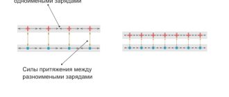
At the very beginning of the charging transition period, the voltage between the plates of the capacitor is zero. As soon as charged particles begin to appear on the plates, a voltage arises between unlike charges. The reason for this is the dielectric between the plates, which “prevents” charges with opposite signs tending to each other from moving to the other side of the capacitor.
At the initial stage of charging, the voltage rises quickly because the high current very quickly increases the number of charged particles on the plates. The more the capacitor is charged, the lower the current, and the slower the voltage rises. At the end of the transition period, the voltage on the capacitor will completely stop growing and will be equal to the voltage on the power source.
As can be seen in the graph, the capacitor current directly depends on the change in voltage.
The formula for finding the capacitor current during the transition period is:
- Ic - capacitor current
- C - Capacitance of the capacitor
- Vc/t – Change in voltage across the capacitor over a period of time
It's better to check first
First, this element needs to be de-energized. It is clear that there is no need to deprive it of its power source. It is enough to turn off the electrical appliance and disconnect the plug from the socket. If you approach this issue radically, then for safety you can turn off all the circuit breakers at the switchboard that are responsible for supplying electricity to the room.
Now we need a special device - a multimeter - to find out whether the capacitor is charged.
- Select the mode for measuring DC voltage (direct current).
- We set the device knob to the maximum voltage measurement level.
- We connect the multimeter probes to the contacts of the electronic component. As a rule, two rods protrude from it. It is to them that you need to connect both probes of the detector. You need to press firmly enough so that digital readings appear on the device display. It makes no difference which probe goes to which contact. The resulting value will be the same in both cases.
We need to understand what voltage is at the terminals of the element. Depending on the indications, the discharge method is selected:
- If the reading is less than 10 volts, there is no need to discharge.
- If the display shows measurements between 10–99 volts, you can discharge it with a screwdriver.
- If values are 100 volts or higher, it is recommended to use a discharge device.
Safe Capacitor Discharge
Currently, we are surrounded by a huge amount of electronic equipment, an integral part of which are capacitors. They are present in any electronic equipment (special purpose) and household electrical appliances (general purpose). By connecting to an energy source, capacitors store electrical charge to power various devices or as a charge source.
It must be taken into account that before disassembling or repairing the device, the capacitor must be discharged, since a sharp increase in current can lead to a short circuit of an undischarged capacitor. This will damage part or all of the circuit components, resulting in electric shock, fire, or explosion.
Moreover, the size of the negative results is directly proportional to the capacitance and voltage of the capacitor. Therefore, to remove the capacitor from the circuit, it is necessary to discharge it.
Below are the main criteria to pay attention to when discharging a capacitor, as well as the general procedure for the simplest situations.
How does a capacitor work?
If the question arises about how a capacitor is designed, then they consist of two electrodes (metal plates called “plates”) with a dielectric polarized insulator located between them, which should be a material that does not conduct or poorly transmits electric current (vacuum, ceramics, certain gases, liquids or solids).
Electrical capacitors are used to store charge. When voltage is applied to the electrodes, an electric charge builds up, and on different plates they have equal values, but with opposite potentials. Once the power source is disconnected, an electrical charge is generated on the capacitor as a result of electrostatic attraction.
There are a significant number of species divided into subspecies. The primary principle of dividing capacitors is determined by the dielectric, which determines the technical characteristics: capacitance of the capacitor and its stability, insulation resistance, loss value, etc.
The following types of capacitors are distinguished:
- vacuum;
- with gaseous dielectric;
- with liquid dielectric;
- with a solid inorganic dielectric (glass, ceramics, etc.);
- with solid organic dielectric/solid-state (paper, etc.);
- electrolytic and oxide semiconductor capacitors;
- combined.
Capacitors can also be classified according to their ability to change capacitance. The vast majority of capacitors have a constant capacitance, which decreases over time for natural reasons.
There are capacitors that allow you to adjust the capacitance mechanically, by temperature or through electrical voltage. In the third type of capacitors, the capacitance is adjusted slightly once or periodically, but does not change during use.
Each type of such device has its own specific area of application. Safe discharge of a capacitor is determined, among other things, by its design features. For example, an integrated circuit contains a ceramic capacitor (ceramic plates on which electrodes are attached).
To discharge such capacitors, it is necessary to use a load with a significant resistance size.
Capacitor parameters
To understand how to discharge a capacitor, you need to familiarize yourself with the data indicated on the case. To properly discharge a capacitor, it is important to take into account all its parameters: nominal capacitance, tolerances and losses, permissible voltage, load, frequency and some additional characteristics.
The most important parameter for safe discharging is the capacitance of the capacitor. It is defined as the potential for charge accumulation in the form of an electric field, which is directly proportional to the voltage between the plates of the plates, the dielectric constant of the dielectric and the area of the plates, having an inverse relationship with the size of the dielectric (distance between the plates).
To increase the capacity, the capacitors are connected in parallel; in this case, the capacity of the battery is equal to the capacity of the capacitors included in its composition. The unit of capacitance of a capacitor is the farad: if the capacitance is 1 farad, then it can generate 1 volt. The capacitance on the case is a nominal value, which is practically unattainable, therefore the tolerance is indicated as a percentage.
Losses are measured by the reduction in energy resulting from work. Determined by the dielectric used and the presence of defects. Capacitors with a vacuum dielectric have the lowest losses, while aluminum ones have the highest.
An ideal dielectric should completely isolate the plates from each other, eliminating the conduction of electric current, but such a material could not be created even in laboratory conditions.
How to discharge a capacitor
So, we have decided that the discharge of a capacitor is determined by its capacity and design. It must be taken into account that the higher the capacitor level, the more caution is needed when discharging, since a short circuit will result in a minimum loss of the capacitor, which will simply burn out, or may lead to an explosion or electric shock.
Safe discharge of the capacitor can only occur after disconnecting the device from the power supply (from the outlet, battery, generator, etc.). To remove the capacitor, please refer to the device's instruction manual. In this case, do not touch the contacts - residual voltage will lead to burns or electric shock. It is necessary to determine whether the capacitor is charged using a multimeter.
This is carried out in the DC (direct current) voltage measurement mode and, having set the maximum level of the indicator, we connect the probes to the contacts. Depending on the result, the discharge method is selected:
- if the result is less than 10 volts, there is no need to discharge;
- if from 10 to 99 volts (small capacitor) - you can use a resistive load, for example, close the contacts with a screwdriver with an insulating handle (there should be no damage to the handle, since in this case there is a risk of electric shock);
- if the value is from 100 volts, a discharge device is needed.
To discharge the device, you need to connect a high resistance load to the plates. In this case, it will take longer to reduce the charge accumulated by the capacitor. The discharge period is determined by two factors: the capacitance of the capacitor and the value of the resistance to which it discharges the charge.
The higher the resistance level, the longer it will take to fully discharge. The reason for this is that at a high level of resistance, the discharge current is small, which means the volume of charge on the capacitor plates decreases little by little.
The charge level decreases at a slower rate if the capacitor has a large capacitance. This occurs as a result of the fact that with a large capacitance, the capacitor plates contain a larger amount of electricity (more charge) and a significant period of time is required to remove the charge.
When a capacitor is discharged, all the energy of the electric field is converted into thermal energy, in other words, electricity heats the resistance through which the capacitor is discharged. And the higher the capacitance of the capacitor and the voltage on its plates, the greater the energy of the electric field of the capacitor will be.
The smaller the resistor that is used for these purposes, the less time it takes to completely discharge. For better understanding, let's give an example. For example, the capacitance of the capacitor is 10 pF, and the resistor has a resistance of 1 kOhm. In this case, the discharge will take 0.01 s.
But it must be taken into account that in order to safely discharge the capacitor, you need to select a resistor of appropriate power, otherwise it may burn out. So, in the case of small components, it will be enough to use a resistor with a power of 5 W and a resistance of 1 kOhm. As an option, we can offer the SR PASSIVES MOF5WS-1K model.
And if we are talking about large blocks, say three-phase energy, then the discharge should be carried out using a YDY 4 mm2 cable by short-circuiting the individual phases of the element to the PE wire.
FKP2-10N/100 Capacitor: polypropylene; 10nF; 5mm; ±10%; 6.5x8x7.2mm; 63VAC
CC-10/100 Capacitor: ceramic; 10pF; 100V; C0G; ±10%; THT; 5mm
DIY discharge device
Before measuring the capacity, check the condensers for breakdown or leakage, or if you need to replace a faulty element, you need to discharge it. It is especially important to make the correct discharge for high-voltage, high-capacity radio components. The accumulated energy can persist for a long time and improper dismantling or storage can pose a threat to life.
An inexpensive, easy-to-implement electronic device can be assembled to safely discharge high-voltage capacitors. It discharges quite efficiently and safely.
Let's look at its circuit diagram:
The voltage from the high-voltage capacitor is supplied to the quenching resistor R1 and then goes to a double-sided diode voltage limiter.
The diode limiter itself consists of two parallel chains of diodes D1-D3 and D4-D6. This is done in order to remove a voltage of about 2 volts from any diode in the circuit for the operation of LED indicators D7, D8. The incoming current to the LEDs is limited by resistor R2.
The LED starts the process of discharging the high-voltage capacitor to a safe voltage of about two volts.
The discharge process may take some time from 10 seconds. and more. The discharge time depends on the capacity of the connected condenser and what residual voltage remains in it.
As soon as the LED goes out, you can carry out the final discharge by short-circuiting the terminals of the radio component using a screwdriver.
The scheme is quite workable.
The entire board can be assembled independently and placed in a plastic case.
Purpose and functions of capacitors
The capacitor plays a huge role in both analog and digital technology. They are electrolytic and ceramic, and differ in their properties, but not in their overall concept. Examples of using:
- Filters high-frequency interference;
- Reduces and smoothes pulsations;
- Separates the signal into constant and variable components;
- Accumulates energy;
- Can be used as a voltage reference;
- Creates resonance with the inductor to amplify the signal.
Examples of using
In amplifiers they are usually used to protect subwoofers, power filtering, thermal stabilization and separation of DC and AC components. And electrolytic ones in autonomous circuits with microcontrollers can provide power for a long time due to their large capacity.
In this circuit, transistor VT1 is constantly open to amplify the sound without distortion. But if the input gets stuck or a direct current flows into it, the transistor will open, go into saturation and overheat. To prevent this, you need a capacitor. C1 allows you to separate the constant component from the variable. The alternating signal easily passes to the base of the transistor, but the constant signal does not.
C2, together with resistor R3, performs the function of thermal stabilization. When the amplifier is running, the transistor gets hot. This may introduce distortion into the signal. Therefore, resistor R3 helps maintain the operating point when heating. But when the transistor is cold and stabilization is not required, a resistor can reduce the power of the amplifier. Therefore, C2 comes into play. It conducts the amplified signal through itself by shunting a resistor, thereby not reducing the rated power of the circuit. If its capacitance is lower than designed, it will begin to introduce phase distortion into the output signal.
For the scheme to work well, good nutrition is a must. When a circuit consumes more current at peak values, it is always a heavy load on the power supply. C3 filters power interference and helps reduce the load. The larger the capacitance, the better the sound, but up to certain values, it all depends on the circuit.
And the power supplies use the same principle as in the previous power supply scheme, but here the capacity is needed much more. In this circuit, the capacitance of the electrolyte can be either 1000 μF or 10,000 μF.
You can also connect ceramic capacitors in parallel to the diode bridge, which will bypass the circuit from high-frequency interference and noise from the 220 V network.
Phase distortion
A capacitor can distort the AC signal's phase. This occurs due to incorrect calculation of capacitance, total resistance and interaction with other radio components. We should not forget that any radio component has both reactive and active resistance.
Source
My-chip.info — Diary of a beginning TV master
Hello friends. Probably, the first entry on my blog should have been an article about safety precautions when repairing televisions and other equipment. But to the extent that this question was obvious to me, I did not attach any importance to it, but in vain. So in this article I will try to correct my omission.
To begin with, I want to say that you do all manipulations with the repair of equipment at your own peril and risk, since lack of knowledge or uncertainty in these matters can lead to a complete loss of functionality of the equipment, and neglect of safety rules can lead to injuries, or God, to more severe consequences.
In the literature, the following precautions are highlighted:
When a person is struck by current flowing from one hand to the other, cardiac arrest is possible. Do not touch the elements of a working TV with both hands. An electric shock can also occur if you touch the TV with one hand and a grounded radiator with the other. Therefore, it is prohibited to repair televisions near grounded central heating radiators, water pipes, etc.
The most serious electric shock occurs when current flows through the body in the direction from the arms to the legs. Therefore, it is prohibited to repair televisions in damp areas or in areas with cement or other conductive floors.
To reduce the risk of electric shock, the repairman should stand on a dielectric mat.
In all cases of working with the TV turned on, when there is a danger of touching live parts, it is necessary to use a tool with insulated handles. The repairman must wear long sleeves or oversleeves.
All manipulations while the TV is on are performed with only one hand.
When repairing a switching power supply, the TV should be connected to the network through a 220 V / 220 V isolation transformer.
When making adjustments with the TV turned on, you must be careful not to touch the terminals of the TVS, OS, multiplier, focusing resistor and other parts of the TV that are under voltage above 1000 V.
The TV's electrolytic capacitors retain their charge for some time after the TV is unplugged. Therefore, it is necessary to discharge them, as well as the capacity of the second anode of the kinescope.
When switching to standby mode, the horizontal scan of the TV, as a rule, continues to be supplied with a voltage of 115...150 V, which can cause electric shock.
In the process of performing preventive maintenance or when repairing a TV in areas of the horizontal scan circuit or switching power supply that have powerful or high-voltage circuits, it is necessary to ensure the required insulation gaps, the quality of installation and soldering, eliminating the occurrence of corona discharge, breakdowns or sparks.
By wiping, it is necessary to remove accumulated dust on high-voltage electrical components, which reduces their electrical insulating properties. Repairing and checking a live TV is permitted only in cases where it is impossible to carry out work with the TV disconnected from the network (adjustment, measuring modes, finding false contacts, etc.).
When repairing, complete composure and care are required. Therefore, smoking and listening to loud music while repairing a TV is unacceptable.
On some points, I’ll add a little of my own. When repairing TVs, regardless of whether we are repairing the power supply, frame, line, or other part of the TV, we must discharge the mains capacitor. It can be 10 µF, 22 µF, 47 µF, 100 µF, 220 µF, 470 µF at 400V, or 450V. It is placed after the diode bridge in the power supply, and very often reminds itself of itself with an electric shock when the TV is turned off, when we simply turn the board over, or change the same frame chip, and accidentally touch it by the capacitor terminals. Believe me, the charge can be stored there for a very long time, and the sensations when receiving an electric shock can be called pleasant;
Discharging the mains capacitor
I discharge the mains capacitor in 2 ways. The first method is to use a screwdriver to close the plus and minus of the capacitor, after which a good discharge is visible and audible. I don’t really like this method, since sometimes a trace of the discharge remains on the board. The second method is a discharge using an incandescent lamp. When repairing a power supply, I always have a socket on my table with a 60 or 100W 220V lamp screwed in. At work, I use it as a load for the power supply, and also discharge the mains capacitors. When a lamp is connected to a charged capacitor, it flashes for a second and goes out, after which the capacitor can be considered discharged. Sometimes I actually forget to do this, after which I pay with a shock in my hand, which quickly sobers up my brain and organizes my thoughts.
Discharging the kinescope
To discharge the kinescope, I use a special probe, at one end of which there is a crocodile, which clings to the kinescope bandage (a steel wire with a spring on the kinescope), the other end of the probe, made of a felt-tip pen with a resistance inside, is connected under the suction cup to the antennae. I hold the dipstick for about a minute, then I climb to remove the suction cup. I don’t remember what resistance value, I made the probe a long time ago, it will be interesting, I’ll take it apart and take a look. You can also discharge it with a simple probe from the tester, connecting one side of the probe to the bandage, the other under the suction cup until it clicks, but in this way the tuner on my TV once refused to work. It was probably filled with static.
That's all I wanted to write in this article. I wish you successful repairs, without injuries.
All the tools and consumables that I use in repairs are located here.
If you have any questions about repairing television equipment, you can ask them on our new forum.
( 9 ratings, average: 5.00 out of 5)
Tips and warnings
After the discharge process is completed, you can wrap its terminals with foil so that this radio component remains discharged. All capacitors can eventually discharge on their own after a few days, provided they are not connected to external power sources. But it is always better to assume that they are in a charged state and a test discharge will not be superfluous. It is necessary to constantly remember that large radio components that switch electricity are very dangerous.
Working with such radio components requires professional skills. Always take safety precautions when working with electrical devices.
What affects the voltage of capacitors
For a charge to occur, the two-terminal network must be connected to an electrical circuit with direct current. For this purpose, a generator can be used, each of which has internal resistance. During a short circuit, the device is charged and a charge appears between its plates. Therefore, the voltage of capacitors is affected by internal resistance. It is also influenced by temperature fluctuations - the higher the heating, the lower the nominal voltage.
Important! The voltage of capacitors is greatly influenced by leakage current. Contrary to popular belief, a dielectric allows a small amount of electrical current to pass through, causing it to lose its initial charge over time and the voltage eventually drops slightly.
Description of the impact on the indicator
Discharge with a screwdriver
First we need a suitable screwdriver with an insulating handle. As a rule, the handles are made of rubber or plastic. Both materials are capable of creating a safe barrier between the hand and the metal part of the screwdriver.
If you are not sure that you have an insulating screwdriver, it is recommended to buy a new one that has a logo with the maximum permissible voltage.
Such tools are sold in the electrical goods department of any hardware department. Both a flathead and a Phillips screwdriver will do.
Now the discharge process itself.
- Grasp the element with one hand at the base, without squeezing too much;
- Place a screwdriver on both terminals;
- A discharge sound and slight sparking will be heard.
Hold the screwdriver so that it touches both legs at the same time, only then the discharge process will occur normally.
To check, you can close the terminals with a screwdriver again.
You can check the degree of discharge with the same multimeter.
Characteristics and properties
Capacitor parameters that are used to create and repair electronic devices include:
- Capacity - C. Determines the amount of charge that the device holds. The value of the nominal capacity is indicated on the case. To create the required values, the elements are included in the circuit in parallel or in series. Operational values do not coincide with calculated values.
- Resonant frequency - fр. If the current frequency is greater than the resonant one, then the inductive properties of the element appear. This makes work difficult. To ensure the design power in the circuit, it is reasonable to use a capacitor at frequencies below resonant values.
- Rated voltage - Un. To prevent breakdown of the element, the operating voltage is set less than the rated voltage. The parameter is indicated on the capacitor body.
- Polarity. If the connection is incorrect, breakdown and failure will occur.
- Electrical insulation resistance - Rd. Determines the leakage current of the device. In devices, parts are located close to each other. At high leakage current, parasitic connections in the circuits are possible. This leads to malfunctions. Leakage current worsens the capacitive properties of the element.
- Temperature coefficient - TKE. The value determines how the capacitance of the device changes with fluctuations in ambient temperature. The parameter is used when developing devices for operation in harsh climatic conditions.
- Parasitic piezoelectric effect. Some types of capacitors create noise in devices when deformed.
Characteristics of capacitors
The main characteristic of a device is capacity, that is, the amount of energy that it can accumulate in the form of electrons. The total number of charges on the plates determines the capacitance value of the capacitor.
Note ! The capacitance depends on the area of the plates and the dielectric constant of the material. The larger the area of the capacitor plates, the more charged particles can fit on them and the higher the capacitance.
Capacity
The most important characteristics include specific capacitance, density, nominal charge force and polarity. Additional parameters include the number of phases, capacitor installation method, operating temperature, active electric current of alternating or direct type.
In electrical engineering, there are also concepts of negative factors that distort the operating properties of an oscillatory circuit. These include electrical resistance and equivalent series inductance. An example of a negative criterion is an indicator showing a drop in charge after a power outage.
You may be interested in this All about current and its frequency
How does he work
If you disassemble the capacitor, its structure is quite simple. These are two electrodes separated by a dielectric material:
- by air,
- ceramic material,
- impregnated paper.
The capacitor plates act as electrodes. It is in them that the process of accumulation of electrical energy occurs from the moment voltage is applied to the plates. If voltage is not applied, then under the influence of electrostatic attraction, the accumulated energy is stored on the plates of the capacitor.
Permanent type condensers are divided into:
- Film. They consist of a three-layer film according to the electrode-dielectric-electrode scheme. The film is rolled up and placed in the housing. They are widely used in electrical circuits of household appliances.
- Ceramic. They consist of ceramic plates with metal electrodes. To discharge them, it is better to use a load with high resistance.
The unit of capacity of this element is considered to be the farad. That is, if a conductor has a capacity of 1 farad, then it is capable of generating 1 volt.
In electronics and electrical engineering, elements are used whose capacitance can be measured:
- picofarads,
- nanofarads,
- microfarads,
- millifarads.
The capacity indicated on the element’s body is a nominal value that is practically impossible to obtain. Therefore, the percentage tolerance of its capacitance is indicated on the capacitor. This should be understood as the percentage deviation of the real value from the nominal value.
How to discharge correctly
In order to find out how to properly discharge a capacitor, you need to keep in mind all those parameters that are inherent in a specific element, namely
- Nominal capacity;
- Capacity tolerances;
- Permissible alternating voltage;
- Dielectric losses;
- Temperature coefficient;
- Permitted impulse load;
- Rated power;
- Frequency.
The most important parameter for the safe discharge of this electronic element is capacity.
How to discharge high-voltage non-polar capacitors without damaging the capacitors themselves?
There is about 450VAC 700uF (connected in parallel), no matter where or how, the main thing is that we have charged capacitors and they need to be discharged. The option with shorted terminals is immediately bypassed - sooner or later this will kill the capacitors, and they will be charged and discharged frequently
The discharge should occur in 1-3 minutes maximum
Zero # 2022.09.30 07:01 0
User replies: score 0 : 0 won't hit anything
Well, then use a shunt of a few kilo-ohms or so, what’s the problem?
Oxotnick # 2022.09.30 20:45 0
User Answers:Simply….
Resistor 100 kOhm 2W parallel to the conductors
Olenka # 2022.10.01 11:40 0
User Answers: Balotelli anyway)
Have you tried using a resistor? Discharge time to 95% (those up to 5% of residual charge) t = 3 RC
Kradun # 2022.10.01 18:44 0
User Answers: Two-wheeled ****
These are by no means high-voltage capacitors...
DolmakimiOglan # 2022.10.02 01:06 0
User Answers: Lights up.
When operating in a 220 V network, as a starting capacitor in an engine, a current of at least 50 A will flow through it. The capacitance of a 700 µF capacitor will be about 4-5 Ohms. Therefore, the game is not worth the candle. You can discharge through a 30 Ohm resistor, preferably a 10 Watt. The flash lamp uses an 800 uF, 450 V capacitor and it discharges with almost a short circuit and nothing! Considering the huge area of the capacitor plates, the danger is only for the conductors leading to them. Yes, and even then, it is most likely exaggerated.
Elvis # 2022.10.02 06:54 0
User Answers: Why pay attention to a former chess player who has gone crazy?
well)))) if you have to, tell me - no answer - straight))))) - in public here!!!! vivalostioz # 2022.10.02 23:26 0
User answers: Free education and medicine...practically none, a rare product in rare salads on rare holiday tables)...Yandex to help!
Through a 5-10 kOhm resistor
BOKSYOR # 2022.10.03 01:05 0
User Replies:Lady Gaga
700uF/450V???? Two series-connected 60-100 watt lamps and the whole problem... or a 500 ohm 10 watt resistor, even a simple wire-wound one! You won’t even see sparks, but it’s painless for the wires and the resistor itself... it won’t even heat up... I did this myself when I soldered the drive at night and everyone was asleep... By the way: Kander won’t give a damn even from the short circuit!!! If it’s non-polar! Tested for years)))
Kill_Me_Gently # 2022.10.03 05:19 0
User Answers: I just took advantage of the opportunity to correct my figure - both ours and yours.
This is a large capacity, you cannot short-circuit, a resistor of about 10 - 50 kohm can be equipped with a thyristor, press the button, and there is no problem...
Zoot # 2022.10.03 05:51 0
User questions: Why is it necessary to undress completely in front of students before surgery, maybe I don’t want to be stared at? I’m constantly nervous about work, I don’t sleep well, I’m losing weight. I work as a teacher at school and the work is very stressful. Which is better i5 8400 or Ryzen 5 2600?
actually using a rod with a resistor and discharging it..
PEPBI3TSIK # 2022.10.03 09:33 0
User Answers:Your roof is on fire - call 01! You need a roof - call 02! You've gone crazy - call 03! Do you need......no.. they disappear somewhere on their own)
Bridge the resistance.
BRIQADIR # 2022.10.04 13:55 0
User replies:hate...It's difficult to find a song based on your information. Try online music recognition programs: Tunatic,...An ax to the head
I advise you to read this
WARLOCK # 2022.10.05 12:17 0
User replies: “...people stopped...” People, imagine, didn’t even start.
2 incandescent lamps 220V 100W in series. I turned on the toggle switch - the discharge began, and at the same time the indication began. If they go out completely, it means they are discharged
KRUTOY # 2022.10.06 00:29 0
User's responses: He wants to quickly get drunk on the road... You look through the sight... you aim... you shoot.. BINGOO... but no, you missed (that's how the sight works: D... Oooh, his look of loving eyes can incinerate...
Starting 700uF... This is a 7.5 kW motor. How will your network hold up? There, the starting current will sag the entire line, and the neighbors along the entire street will be indignant....
RC circuit time constant
But the fact is that we cannot observe the process of discharging a capacitor just by looking at the RC circuit. To do this, we need a digital oscilloscope with a signal recording function. Fortunately, I already have a place for this device on my desktop:
So, the action plan will be this: we will charge the capacitor using the power supply, and then discharge it through a resistor and watch the oscillogram of how the capacitor is discharged.
Let's assemble a classic circuit that can be found in any electronics textbook:
at this moment we charge the capacitor
then we switch the toggle switch S to another position and discharge the capacitor, observing the process of discharging the capacitor on an oscilloscope
I think this is all clear. Well, let's start assembling.
We take a breadboard and assemble the circuit. I took a capacitor with a capacity of 100 μF, and a resistor of 1 KiloOhm.
Instead of the S toggle switch, I will manually toss the yellow wire.
Well, that's it, we hook the oscilloscope probe to the resistor
and watch the oscillogram of how the capacitor is discharged.
Those who are reading about RC circuits for the first time, I think, are a little surprised. Logically, the discharge should proceed in a straight line, but here we see a problem. The discharge occurs according to the so-called exponential . Since I do not like algebra and mathematical analysis, I will not give various mathematical calculations. By the way, what is an exponent? Well, an exponential is a graph of the function “e to the power of x”. In short, everyone went to school, you know better